Removing Satellite Particles and Partially Sintered Powder from Titanium SLM Parts by Abrasive Blasting
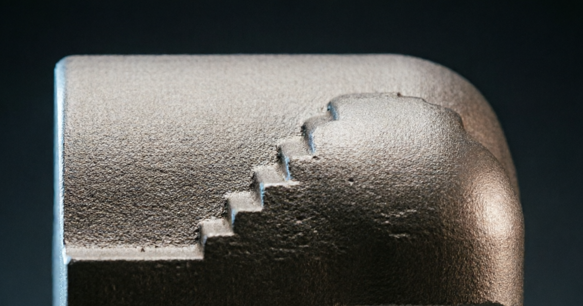
Satellite particles are small, partially fused powder spheres that adhere to the surface of SLM titanium parts after the build process. Though they appear minor under casual inspection, satellites act as fatigue initiation sites in aerospace applications, compromise osseointegration in medical implants, and create dimensional non-conformances in precision fits. This guide provides the technical basis for understanding satellite formation, selecting the right media, and applying the controlled low-energy blast protocol required to dislodge them without embedding new particles or damaging the surface beneath.
1. Understanding Satellite Formation in the SLM Process
During selective laser melting, the laser scans the powder bed at speeds of 500–2,000 mm/s, creating a narrow melt track approximately 100–150 μm wide. The intense energy of the laser creates a complex vapor plume above the melt pool, which ejects fine metallic droplets (spatter) at velocities of 1–10 m/s across the powder bed. Some of these droplets land on previously solidified surfaces and fuse partially — not fully melting in, but bonding sufficiently to survive the build process and post-build depowdering. These are “spatter-derived” satellite particles.
A second class of satellite forms at the melt track perimeter, where powder particles adjacent to the melt pool absorb sufficient radiant and conductive heat to sinter together and bond to the solidified melt track edge without fully melting. These “thermally bonded” satellites are most prevalent on downfacing surfaces, where the melt pool is supported by loose powder rather than previously solidified material, and on near-vertical side surfaces where the laser scan boundary intersects with the powder bed at a low angle. Under scanning electron microscopy, both satellite types appear as spherical or near-spherical protrusions with diameters ranging from 5 to 80 μm, sometimes carrying their own smaller secondary satellites.
Satellite distribution is not uniform across the part surface. Upskin surfaces (facing upward during the build) receive better laser energy and are generally cleaner, with satellite density typically 30–50% lower than downfacing surfaces. Internal channel walls and recessed features collect the highest satellite density because spatter is more likely to deposit in recesses and the thermal conditions near internal features tend to favor partial sintering.
2. Why Satellites Matter: Performance and Regulatory Consequences
In aerospace applications, satellite particles create stress concentration features on cyclically loaded surfaces. Even a 20 μm spherical protrusion at the surface of a Ti-6Al-4V structural component represents a geometry change with a theoretical stress concentration factor (Kt) of 1.5–2.5 depending on the surrounding surface topography. Under high-cycle fatigue loading, stress concentrations of this magnitude are sufficient to nucleate fatigue cracks at stress amplitudes well below the smooth-specimen fatigue limit. Multiple studies have demonstrated that satellite particles on SLM titanium reduce the high-cycle fatigue limit by 15–35% compared to surfaces from which satellites have been removed — a consequence that is incompatible with aerospace fatigue life requirements.
In orthopedic and dental implant applications, satellites have two separate failure modes. Particles that become dislodged in the body’s biological environment generate metallic wear debris, which can trigger periprosthetic inflammation (aseptic loosening), particulate disease, and in severe cases systemic toxicity. Particles that remain on the surface during implantation create an irregular surface topography that sits outside the Ra 1–4 μm range optimal for osseointegration, compromising the long-term fixation quality of the implant. Regulatory submissions for orthopedic titanium SLM implants must demonstrate particle-free surfaces, and ISO 13485 quality management systems typically require this as a documented process output.
3. Characterizing the Satellite Distribution on Your Part
Before setting blast parameters, characterize the satellite distribution on the specific part geometry. This is best done by examining a first-article build at low magnification (20–50× stereomicroscope) across all surface types: upskin, downskin, vertical, and internal-channel-adjacent areas. Note which areas carry the highest satellite density — these will require longer dwell time or more blast passes. Areas with thin walls or delicate lattice struts require reduced blast pressure to avoid deformation.
For medical implant validation, quantitative satellite characterization using SEM image analysis at defined locations (per a standardized sampling plan) provides the baseline against which post-blast surface cleanliness is verified. The acceptance criterion should specify maximum allowable satellite count per unit area, maximum individual satellite diameter, and confirmed absence of satellites larger than a defined threshold (typically 50 μm for implant applications).
Note also whether the as-built surface carries alpha-case in addition to satellite particles. If alpha-case is present at significant depth (>30 μm), the satellite removal blast protocol must be preceded by the alpha-case removal sequence described in our guide on alpha-case removal from SLM titanium parts using abrasive blasting. Attempting to achieve the fine surface finish required for satellite removal before alpha-case is addressed is counterproductive — the coarse alpha-case removal blast will displace any satellites, but it also roughs up the surface beyond the satellite-removal parameters.
4. Media Selection: Low Energy, High Precision
The key challenge of satellite removal is applying exactly enough energy to break the sintered bond between the satellite and the base surface without embedding media particles into the titanium or cold-working the satellite material into the surface — which would make it even more firmly attached. This requires media that are small enough to deliver localized impact at the satellite-to-surface bond, soft enough that they deform preferentially on impact rather than gouging the substrate, and propelled at low enough velocity to prevent re-embedding.
Two media types meet these criteria:
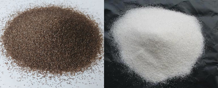
- Fine aluminum oxide (mesh 150–200, mean particle size 75–100 μm) at low pressure (30–50 PSI). The angular morphology of fine Al₂OΆ creates a micro-cutting action that effectively breaks the sintered bond at the satellite attachment point. The relatively hard particles (Mohs 9) can embed in titanium if used at high pressure — which is why pressure limitation is critical. At 30–50 PSI and 150–200 mm standoff, the impact energy is sufficient for satellite dislodgement but below the threshold for significant media embedment.
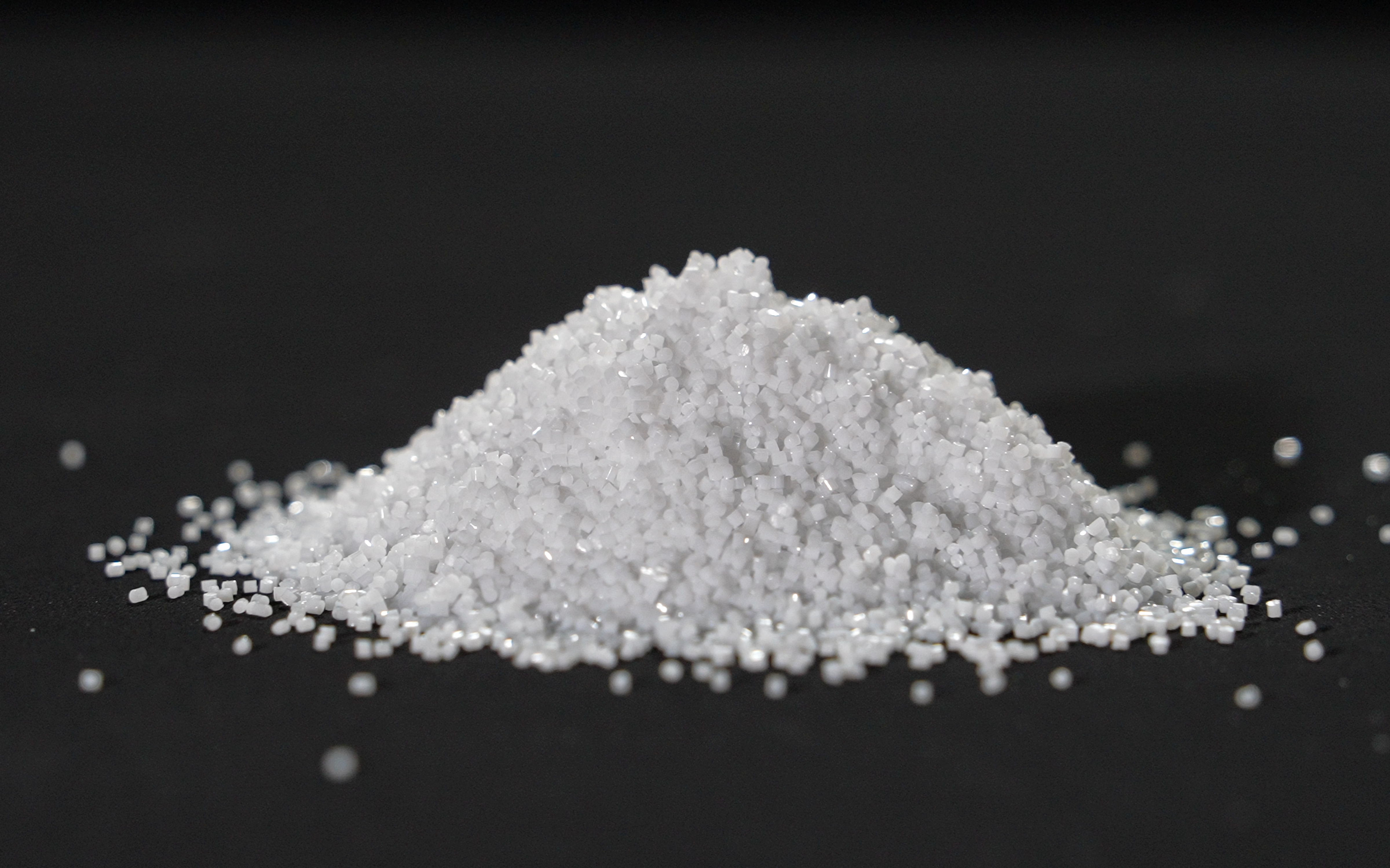
- Fine glass beads (mesh 150–200, mean particle size 75–100 μm) at 35–50 PSI. Spherical glass beads deliver a gentler, peening-type impact that breaks the satellite bond through cyclic impact rather than cutting. They have lower embedment risk than Al₂OΆ due to their rounded morphology. For medical-grade titanium where alumina contamination is a concern, fine glass beads from a confirmed iron-free source are the preferred choice. Confirm media certification from supplier to ensure absence of ferrous contamination before use on implant-grade parts.
Zirconia beads in the same size range (mesh 150–220) are the premium option for both applications — superior durability, no contamination risk, and effective satellite removal. The higher upfront cost is offset by extended recycling life (2,000–4,000 cycles vs. 400–800 for glass beads).
5. Blast Parameters: Pressure, Distance, Angle, Dwell
| Parameter | Recommended Range | Rationale |
|---|---|---|
| Blast pressure | 30–50 PSI | Sufficient to break sintered bond; below media embedment threshold |
| Standoff distance | 150–200 mm | Reduces impact velocity; increases beam spread for uniform coverage |
| Nozzle angle | 60–75° to surface | Creates shear component at satellite base; avoids direct perpendicular impact that drives embedment |
| Traverse speed | 200–300 mm/min | Controlled dwell; prevents localized overblasting of thin-wall areas |
| Number of passes | 2–4 | Verify satellite removal by in-process inspection after pass 2 |
| Media size | Mesh 150–200 | Must be smaller than lattice cell openings to reach internal satellite deposits |
For areas with thin walls (<0.8 mm) or delicate lattice struts, reduce pressure to 25–35 PSI and increase standoff to 200–250 mm. Perform a test blast on a representative coupon before production blasting of thin-wall sections. The risk of wall deformation from satellite-removal blasting is real on SLM titanium parts with walls thinner than 0.6 mm; for these, wet blasting at lower pressure or vibratory finishing may be the safer alternative.
6. Post-Removal Inspection and Verification
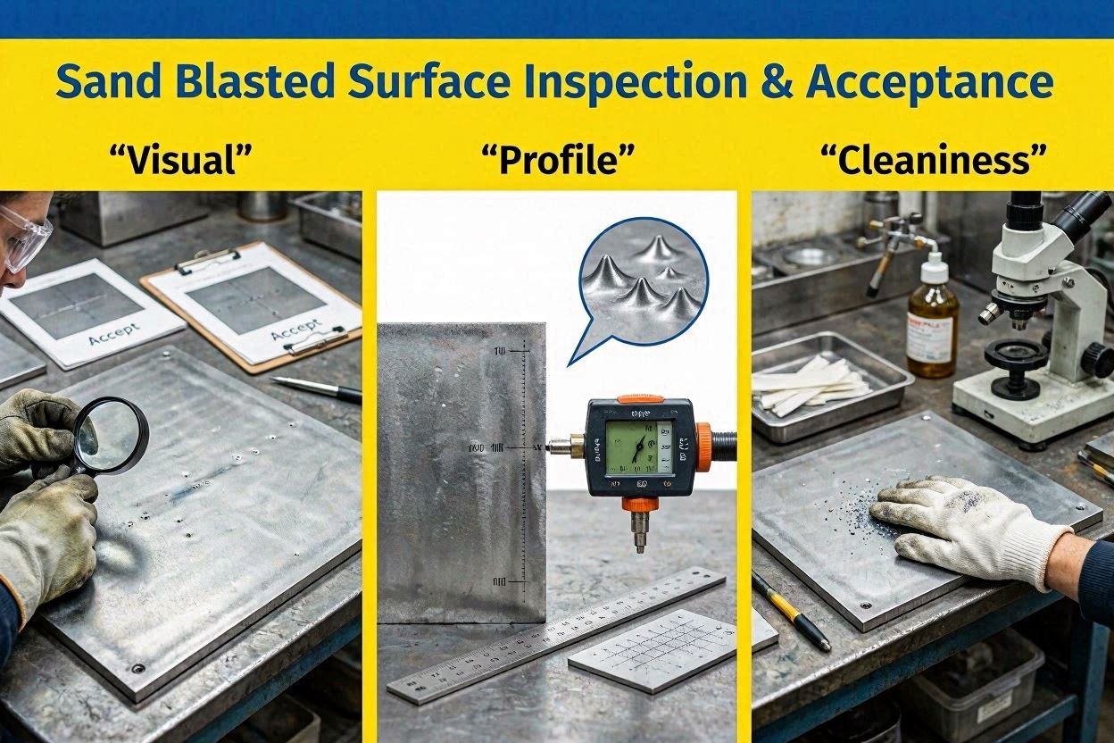
Post-blast inspection for satellite removal combines visual, optical, and for regulated applications, SEM verification. Under a stereomicroscope at 20–50×, confirm that the surface shows a uniform, matte blast texture with no protrusions visible. Areas that previously showed dense satellite coverage should now present the same textured appearance as naturally cleaner upskin surfaces.
For SEM-based quantitative verification (required for most medical implant applications), prepare representative samples at defined build locations and image at 200× with backscattered electron (BSE) contrast, which makes protruding particles more visible by enhancing the topographic contrast. Measure satellite count per field of view and compare against the acceptance criterion defined in the product specification.
Surface roughness measurement after satellite removal should show a modest Ra reduction compared to the as-built surface, primarily due to leveling of the high-point protrusions. If Ra has increased significantly compared to the as-built value, it indicates that the blast pressure was too high and media were impacting and roughening the base surface rather than targeting satellites — reduce pressure and re-evaluate on a new coupon. For Ra measurement methodology on blasted SLM titanium, see our guide on surface roughness measurement for abrasively finished titanium SLM parts.
Satellite removal is a mandatory step before hot isostatic pressing (HIP) to prevent open pore sealing. See our guide on pre-HIP abrasive surface preparation for titanium SLM parts for the complete pre-HIP blasting protocol and rationale.
Frequently Asked Questions
No. While ultrasonic cleaning effectively removes loose, un-bonded powder particles from the SLM surface, satellite particles have a partial metallurgical bond to the surface that ultrasonic cavitation energy cannot break. Ultrasonic cleaning should be used after blast operations as a cleaning step (to remove dislodged debris and media residue), not as a substitute for the blast. For parts where even gentle blasting is not acceptable — such as some thin-wall or flexible lattice geometries — vibratory finishing with fine ceramic or plastic media is an alternative that applies gentler, multidirectional impact to dislodge satellites over extended processing time (30–90 minutes).
For walls thinner than 0.8 mm, the standard satellite-removal pressure range of 30–50 PSI may cause measurable deflection or permanent deformation of wall sections, particularly in SLM titanium where the as-built surface is not as work-hardened as a machined surface. For walls in the 0.5–0.8 mm range, reduce blast pressure to 20–35 PSI and increase standoff distance to 200–250 mm. For walls below 0.5 mm, blast-based satellite removal is not recommended; instead, use vibratory finishing with fine plastic or ceramic media (3–5 mm chip media) in a vibrating bowl for 30–60 minutes at moderate amplitude.
The most practical in-process check is stereomicroscope inspection at 20–50x after each blast pass. Compare the surface appearance of blasted areas to a reference standard (either a defined reference photograph in the process specification or a retained pre-approved sample). For quantitative verification in medical and aerospace applications, SEM imaging at defined locations with backscattered electron contrast provides the documented evidence required by ISO 13485 or AS9100. The acceptance criterion should be defined in the product specification and verified during process validation rather than being determined subjectively by the blast operator.
Yes, significantly. Satellite particles — which can be 20–80 μm tall — contribute to surface height measurements and artificially inflate Ra, Rz, and Sa values. A surface with a satellite density of 5–10 per mm² can show Ra values 2–4 μm higher than the underlying blasted surface would show if satellites were removed. This means that Ra measurement on an as-built or post-depowder surface overestimates the true surface roughness of the base material, and that Ra measurements taken after satellite removal will be lower than as-built Ra even if no aggressive blasting has been done. Always measure Ra after satellite removal for a representative characterization of the finished surface.
Need Specialist Abrasive Media for Titanium SLM Finishing?
Jiangsu Henglihong Technology Co., Ltd. supplies fine aluminum oxide, fine glass beads, and zirconia beads in the mesh 150–220 range, suitable for satellite particle removal from titanium SLM parts across medical and aerospace applications. Contact our team for grade selection and process support.
Contact Our Technical TeamFilters