Removing Support Structures from Metal 3D Printed Parts with Abrasive Blasting
Every metal 3D printed part that contains overhanging features requires support structures — lattice or solid scaffolding melted into the same build that prevents overhangs from collapsing during the build cycle. Support removal is one of the most labour-intensive and technically demanding steps in metal AM post-processing, and it leaves behind surface conditions — cut marks, oxidised heat-affected zones, EDM recast layers, and rough attachment surfaces — that require targeted abrasive blasting treatment before the part meets its surface finish specification. This guide covers the full support removal and blast post-treatment workflow for metal AM components, from initial mechanical cutting to targeted blast treatment and final inspection.
1. Support Structures in Metal AM: The Post-Processing Problem
Metal AM support structures are not an optional design element — they are a physical necessity for any overhanging surface below a critical angle (typically 45° from horizontal for SLM, though this varies by machine and material). Supports anchor the part to the build plate, conduct heat away from the melt pool, and prevent deformation of overhangs and thin features during the build. Without supports, parts with overhangs would collapse, warp, or become dimensionally non-conformant.
The challenge is that these necessary supports must be removed after the build, leaving behind surfaces that are typically worse than any other surface on the part. The support-to-part interface is a deliberately weak zone (typically with a small offset gap or perforated contact area to facilitate manual breaking or cutting), but the removal process always introduces surface damage:
- Cut surfaces from wire EDM: The most common removal method for production metal AM. EDM creates a recast layer (5–20 µm) and heat-affected zone (20–100 µm) at the cut surface, plus thermal oxidation discolouration extending from the cut edge.
- Band-saw or machined cuts: Leave mechanical burrs, rough cut surfaces, and sometimes tool marks on the parent metal surface adjacent to the support cut line.
- Manual fracturing / snap-off: Creates irregular fracture surfaces at the contact points, sometimes with residual support stubs that must be ground away.
- Support witness marks: Even after clean removal, the parent metal surface at the former support attachment zone typically shows a different texture, colour, and Ra value from the surrounding surface, making it readily visible in inspection.
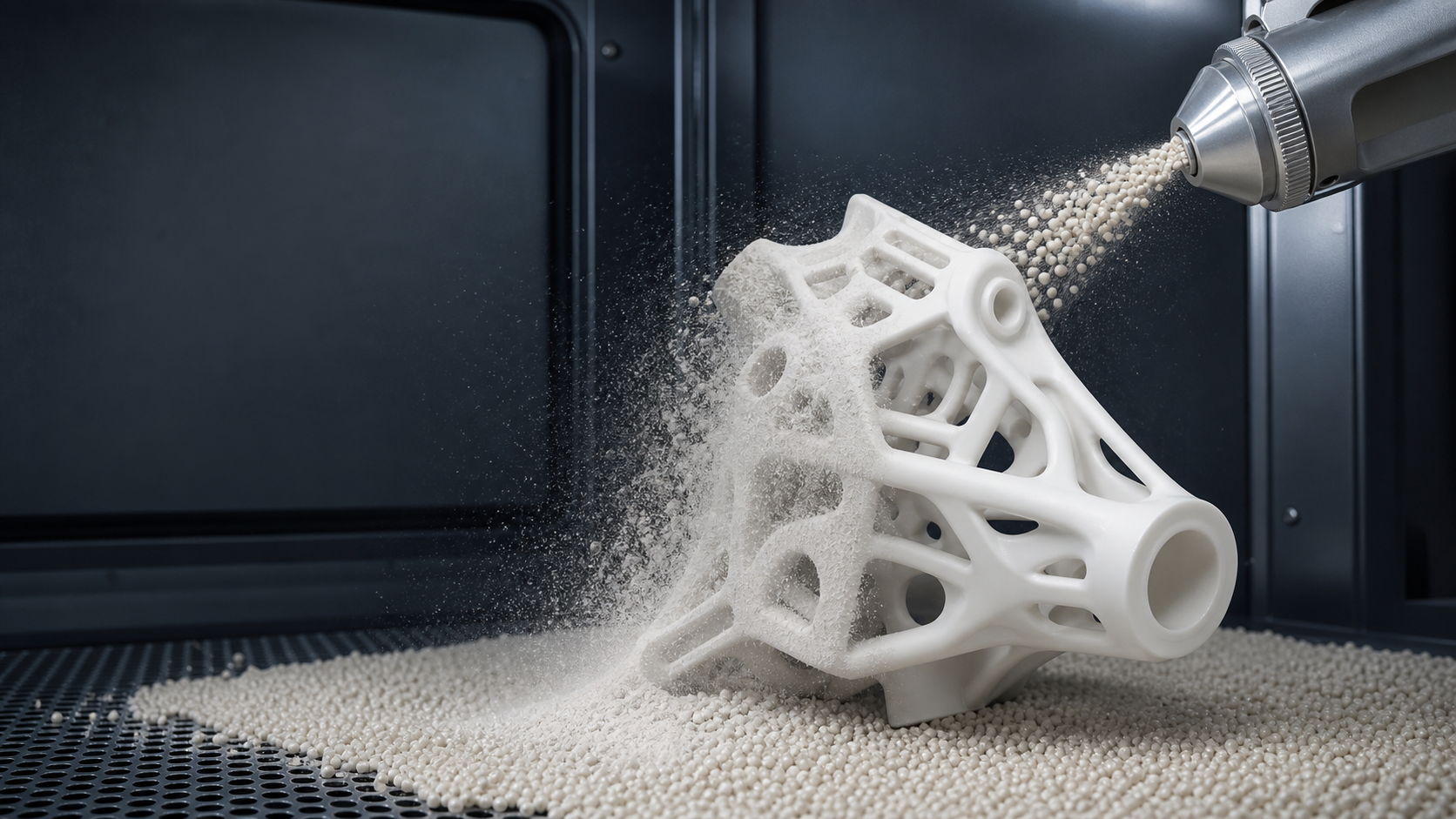
Abrasive blasting is the most effective and scalable method for treating all of these post-removal surface conditions — removing the recast layer, cleaning the oxidised zone, and blending the support attachment area into the surrounding parent surface texture.
2. Mechanical Support Removal: What Comes First
Abrasive blasting follows — it does not replace — mechanical support removal. Before the first blast pass, supports must be removed by one of the following methods:
Wire EDM (Most Common in Production)
Wire electrical discharge machining cuts through the support contact zone with a travelling wire electrode, using electrical sparks to erode material without physical contact force. The advantages are dimensional precision (±0.01 mm) and the ability to cut through thick support cross-sections. The disadvantages are the recast layer and thermal oxidation it leaves behind — which is why post-EDM blasting is always required. Wire EDM is the standard support removal method for high-value production metal AM parts (aerospace components, medical implants, precision tooling).
Band-Saw Cutting
Band-saw cutting is faster and cheaper than EDM for large-cross-section supports. It leaves a mechanical burr and rough cut surface rather than an EDM recast layer, but the surface is still significantly rougher than the parent part surface. Post-saw blasting with Al₂O₃ grit is effective at removing burrs and blending the cut surface.
Manual Fracturing
For thin, blade-type supports (cross-section below 0.5 mm), manual fracturing with pliers or a chisel can break the support at the designed weak interface. This is the fastest method but leaves the most irregular surface at the fracture zone. If the part design includes small tear-off tabs at support contact points, manual fracturing is designed into the support strategy.
The Sequence
The correct post-removal blast sequence: mechanical support removal → targeted blast of support zones → full-part blast pass → inspection. Attempting to blast before all supports are removed is ineffective and can damage the nozzle or clog the blast circuit with large metal fragments.
3. What Abrasive Blasting Achieves After Mechanical Removal
After mechanical support removal, abrasive blasting addresses the following specific surface conditions at support attachment zones:
- Recast layer removal (EDM): The EDM recast layer is a thin, brittle, re-solidified zone that differs chemically and metallurgically from the parent metal. Angular Al₂O₃ grit at 70–90 psi removes this layer by abrasive cutting, exposing the parent metal microstructure. For titanium (where Al₂O₃ cannot be used), glass beads at 70–80 psi require more passes to achieve equivalent recast removal but are effective.
- Thermal oxide removal: The heat-tinted oxide zone extending from the EDM cut is removed by the blasting abrasive, restoring the surface to the appearance of the surrounding blasted metal. Colour uniformity between the support zone and surrounding surface is the visual acceptance criterion.
- Burr and step removal: Cut burrs from band-saw or manual fracturing are removed by the blast abrasive stream. Angular media is more effective for burr removal than spherical glass beads.
- Surface blending: After targeted treatment of support zones, a full-part finishing blast with glass beads at standard parameters creates a uniform texture across both the support attachment zone and the surrounding surface, making the former support location indistinguishable from the surrounding surface in most applications.
4. Media Selection for Support Zone Treatment
Support zone treatment requires more aggressive media than standard surface finishing because the recast layer and thermal oxide are harder and more adherent than normal as-built surface conditions.
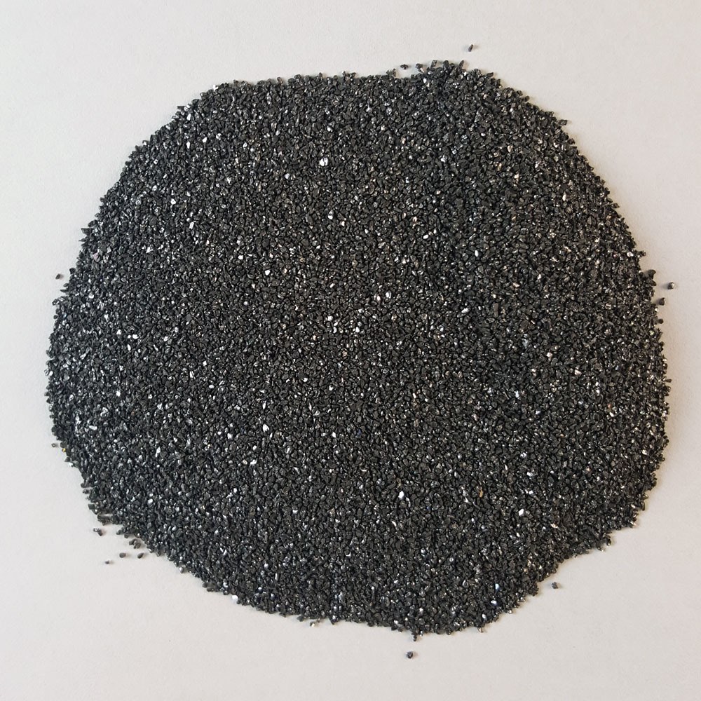
Al₂O₃ Grit (Primary for Steel and Inconel)
Angular Al₂O₃ grit (36–80 mesh) at 70–90 psi is the most effective medium for EDM recast layer removal and burr removal on carbon steel, tool steel, and Inconel AM parts. The angular fracture planes of Al₂O₃ particles act as micro-cutting tools, removing the hard recast layer by cutting rather than deformation. Use 36–60 mesh for heavy recast layers (>15 µm thick) and 80–120 mesh for light recast layers and thermal oxide removal.
Glass Beads (Required for Ti and SS)
For titanium and stainless steel, where iron contamination from Al₂O₃ is not a concern but iron-containing media is prohibited, glass beads at 70–80 psi (100–150 mesh) provide effective recast layer treatment by repeated impact rather than cutting action. Multiple passes are required compared to Al₂O₃ on equivalent recast layers, but the iron-free constraint is non-negotiable for these alloys.
Steel Grit (Only for Carbon Steel AM)
For carbon steel and low-alloy steel AM parts (rare in SLM but increasingly common in directed energy deposition), angular steel grit provides the highest material removal rate and is appropriate for aggressive descaling and support zone treatment where iron contamination is not a concern.
| Alloy | Media for Support Zones | Mesh/Grit | Pressure (psi) | Notes |
|---|---|---|---|---|
| Ti-6Al-4V | Glass beads | 80–120 | 70–80 | Multiple passes; iron-free only |
| 316L Stainless | Glass beads | 80–120 | 65–75 | Ferroxyl test after treatment |
| AlSi10Mg | Glass beads or fine Al₂O₃ | 100–150 | 55–70 | Al₂O₃ for heavier recast; check embedding |
| Inconel 718/625 | Al₂O₃ | 60–80 | 75–90 | Hard alloy; aggressive treatment acceptable |
| Maraging Steel | Al₂O₃ or steel grit | 60–80 | 75–90 | Aggressive treatment; high hardness tolerance |
5. Targeted Blast Protocol for Support Attachment Zones
- Map support attachment zones. Before blasting, identify all support attachment locations on the part and mark them on a routing sheet or the part drawing. This ensures all zones receive targeted treatment and none are missed during the blast operation.
- Set up for targeted blasting. Use a small-diameter nozzle (5–8 mm ID) for precise blast direction. Load the appropriate aggressive media for the alloy (Al₂O₃ or glass beads per the table above). Set pressure at the higher end of the recommended range for support zone treatment.
- Treat each support zone. Direct the blast nozzle at the support attachment surface at 60–80° angle. Move in small circular or overlapping linear passes, maintaining consistent standoff (6–8 inches). Continue until: (a) the recast layer visual appearance (shiny, glassy for EDM; burnished for band-saw) is replaced by the matte, uniform texture of the treated surface, and (b) any discolouration is removed. Typical treatment time per zone: 30–90 seconds.
- Inspect each zone after treatment. Under raking light, the treated zone should show a texture matching the surrounding as-built surface. Any remaining shiny spots, blue/gold discolouration (titanium) or dark brown marks (stainless) indicate incomplete treatment requiring additional blast time.
- Transition to full-part finishing pass. After all support zones are treated to acceptable condition, change to the standard finishing media (glass beads 100–200 mesh) and perform the full-part finishing blast at standard parameters to unify the surface texture across the entire part, including the previously-treated support zones.
6. Full-Part Finishing After Support Zone Treatment
After all support zones have been treated with targeted aggressive blasting, the full-part glass bead finishing pass creates surface uniformity — blending the treated support zones into the surrounding surface so that the former support attachment locations are visually indistinguishable from the rest of the part surface under normal inspection conditions.
The finishing pass uses the same parameters as standard SLM part blasting for the alloy (glass beads 100–200 mesh, 50–75 psi depending on alloy). The duration is the minimum needed for complete surface coverage — typically 3–8 minutes for a production bracket-scale part. Avoid excessive blast time during the finishing pass: the goal is surface uniformity, not additional material removal.
After the finishing pass, the part should display a completely uniform matte appearance with no visible differentiation between support attachment zones and surrounding surfaces. This is the baseline acceptance criterion for visual quality in support removal workflows.
7. Alloy-Specific Considerations
Titanium (Ti-6Al-4V)
Titanium support attachment zones treated by EDM show distinctive golden or blue oxidation colouring that contrasts sharply with the silver-grey of the surrounding as-built or blasted surface. Glass bead blasting (80–120 mesh, 70–80 psi) removes this colouration and the underlying oxide layer. Because iron-free media is mandatory for titanium, the process is slightly less efficient than Al₂O₃ on equivalent recast layers — more passes are needed, but the result is equivalent. After treatment, perform the ferroxyl test on the treated zones specifically to confirm no iron contamination from any tool contact during mechanical removal.
Inconel 718 and 625
Inconel superalloys are among the hardest and most creep-resistant AM alloys, and their support zones can develop heavily oxidised, scale-type layers at EDM-cut surfaces. Al₂O₃ 60–80 mesh at 80–90 psi is required for effective recast layer removal. The high hardness of age-hardened Inconel 718 (HRC 40–48 after aging) means aggressive blasting does not risk surface damage — the alloy tolerates the treatment well.
316L Stainless Steel
Stainless steel support zones show heat tinting (gold, blue, rainbow colours) from EDM thermal effects. Glass beads at 65–75 psi with 100–150 mesh remove the tinting effectively. Perform the ferroxyl test after treatment to confirm no iron contamination was introduced during mechanical support removal. If EDM wire contact with the part surface left iron transfer (possible from wire EDM), additional alkaline cleaning and re-blasting may be required.
8. Internal Support Channels and Complex Geometries
The most challenging support removal scenarios involve supports inside enclosed geometries — bores, cooling channels, hollow structures — where external blasting nozzles cannot reach the attachment zone. This is one of the most significant unresolved challenges in metal AM post-processing.
Available Approaches for Internal Support Treatment
- Abrasive flow machining (AFM): Visco-elastic polymer media loaded with abrasive particles is forced under hydraulic pressure through internal passages. The media conforms to the passage shape and abrades all surfaces it contacts, including internal support attachment zones. AFM is the most widely adopted technology for internal AM surface finishing and support zone treatment. Typical Ra reduction from AFM: 50–70% on internal surfaces of AM parts.
- Wet abrasive blasting with lance nozzles: Flexible hose lances with small nozzle heads (4–8 mm diameter) can access channels with minimum diameter approximately 10–12 mm. For larger accessible channels, this provides a cost-effective solution.
- Electrochemical machining (ECM): For conductive metals, shaped electrodes can remove material from internal surfaces electrochemically. Useful for high-value parts with critical internal surfaces.
- Design for manufacturability: The most effective solution is to minimise or eliminate internal supports through design optimisation, self-supporting overhangs, or splitting the part for separate production and post-processing. This is a process planning decision, not a post-processing fix.
9. Quality Control After Support Removal
- Visual inspection: Under raking light, compare each former support zone to surrounding surface texture. No residual shiny patches, discolouration, or visible recast layer. No step-off between support zone and parent surface should be visible at normal inspection distance (300–500 mm).
- Ra measurement: For controlled applications, measure Ra at support zones specifically and compare to the Ra measured on standard surfaces of the same part. Acceptable if within ±30% of the nominal surface Ra or within the drawing callout Ra range.
- Dimensional check: Confirm that aggressive targeted blasting at support zones has not removed excessive material from the parent part in those areas. For tight-tolerance features near support attachment zones, measure before and after treatment.
- Ferroxyl test (Ti, SS): Apply ferroxyl reagent specifically at support attachment zones where tool contact during mechanical removal may have introduced iron contamination. Document results.
- NDT (for critical aerospace/medical parts): After support removal and blasting, fluorescent penetrant inspection (FPI per ASTM E1417) is performed on many aerospace metal AM parts to confirm absence of cracks at support attachment zones — stress concentration points where cracks can initiate if the removal process was aggressive.
For the full metal AM blasting protocol, see: Shot Blasting Metal 3D Printed Parts: SLM, DMLS, and EBM Post-Processing Protocol. For surface roughness improvement details, see: Improving Ra and Rz on 3D Printed Parts: How Abrasive Blasting Reduces Surface Roughness.
Frequently Asked Questions
Should I blast support attachment zones separately from the rest of the part?
Yes — a targeted blast pass on support attachment zones before the full-part finishing pass is best practice for production metal AM. Support zones start rougher (Ra 20–40 µm at the cut interface) and more oxidised than the surrounding parent surface. A targeted pass with Al₂O₃ 60–80 mesh at 70–90 psi addresses the recast layer and oxidised zone first; then the full-part glass bead pass brings the entire surface to a uniform finish. Skipping the targeted support-zone pass and blasting the whole part at glass bead parameters leaves the support attachment zones rougher than the rest of the surface.
Can abrasive blasting remove attached support structures without prior mechanical removal?
Only in limited cases. For very small, fragile support tabs (thin blade-type supports < 0.5 mm in cross-section) on titanium or Inconel parts, directed high-pressure blasting (Al₂O₃ 60–80 mesh at 80–100 psi, focused nozzle, close standoff of 4–6 inches) can break off the support and simultaneously clean the attachment zone. This approach is used in some dental AM workflows for cobalt-chrome frameworks where EDM is not practical. However, for most production metal AM with robust support structures designed to withstand build forces, the support cross-section is too strong for blasting alone to fracture. Mechanical cutting remains the primary support removal method; blasting is the post-cutting surface treatment.
What blast parameters should I use after wire EDM support removal?
After wire EDM, the cut surface has an EDM recast layer (typically 5–20 µm thick for steel alloys, 2–10 µm for titanium) that is hard, brittle, and oxidised, plus a heat-affected zone extending 20–100 µm below the cut surface. The targeted blast protocol for EDM-cut support zones: Al₂O₃ grit 60–80 mesh (for aggressive recast layer removal) at 70–90 psi, standoff 6–8 inches, nozzle angle 60–80°. Apply until the surface appearance matches the surrounding as-built or blasted surface. For titanium after EDM, use glass beads instead of Al₂O₃ to avoid iron contamination, at 70–80 psi with 80–120 mesh beads.
How do I blast support attachment zones on internal surfaces?
Internal support zones (inside bores, channels, or enclosed cavities) cannot be treated by standard external nozzle blasting. Options include: (1) Wet abrasive slurry blasting using a flexible hose lance with a small nozzle, for accessible internal geometries. (2) Abrasive flow machining (AFM / extrude hone), which forces abrasive-laden polymer through internal passages and removes surface material from all surfaces the flow contacts — including internal support zones. (3) Electrochemical machining (ECM) for conductive metals, which can reach internal surfaces with shaped electrodes. Design-for-AM principles should minimise internal support requirements, as internal support removal and internal surface finishing remain the most significant post-processing challenges in metal AM production.
Why are support attachment surfaces often discoloured after mechanical removal?
The discolouration (commonly golden, blue, or dark brown) at support attachment zones on titanium and stainless steel parts is caused by oxidation during the wire EDM or band-saw cutting process. EDM introduces significant local heating (thousands of degrees at the spark gap) despite the dielectric fluid cooling — sufficient to thermally oxidise the surface of the parent metal at the cut interface. Bead blasting or Al₂O₃ blasting after EDM removal removes this oxide discolouration and the recast layer beneath it. The treated surface should match the colour of the surrounding blasted metal. If discolouration persists after blasting, chemical pickling (acid etching) may be needed to remove heavily oxidised areas.
Does the type of support structure (solid vs lattice vs conical) affect blasting requirements?
Yes — support geometry significantly affects post-blast cleanup requirements. Solid block supports: largest attachment area; highest risk of step-off marks after removal; most material to treat with targeted blasting. Lattice supports: smaller attachment points; lower material marks; faster cleanup; risk of lattice remnants inside complex builds. Conical/blade supports (thin web type): smallest attachment footprint; minimal surface disturbance after removal; fastest blast cleanup. Point supports and breakaway supports (designed to snap): minimal residue but sometimes leave raised witness marks that require targeted treatment. Optimised support design with small touch points significantly reduces the post-blasting work on support attachment zones — a process planning consideration that pays dividends in post-processing time.
Source Blasting Media for Metal AM Support Zone Treatment
Jiangsu Henglihong Technology Co., Ltd. manufactures aluminum oxide grit and glass beads used in support zone treatment for metal AM production. Our technical team can advise on media selection, pressure settings, and sequence protocols for Ti, SS, Inconel, and aluminum AM alloys.
Contact Our Technical TeamPublished July 2026 by Jiangsu Henglihong Technology Co., Ltd. — Specialists in industrial abrasive blasting media for additive manufacturing post-processing.
Filters