Ceramic Media Shapes Guide: How to Choose the Right Chip Geometry for Every Part and Process
An engineering-level reference covering all standard ceramic finishing media shapes — triangle, cylinder, cone, star, sphere, and diagonal variants — with decision frameworks, lodging prevention rules, and part-geometry-to-shape mapping tables.
1. Why Shape Is the Most Overlooked Selection Variable
When engineers first specify ceramic mass finishing media, they typically focus on two variables: abrasive grade (cut rate) and media size. Shape is often treated as a secondary choice — sometimes left to the media supplier’s default recommendation. This is a costly mistake. Media shape determines which surfaces of the workpiece can actually be reached, how efficiently burrs are contacted and removed, and whether the media will become lodged inside the part — rendering the entire batch unusable until the embedded chips are manually extracted.
In practical terms, a perfectly specified cut rate and media size will deliver zero useful work if the chip geometry cannot make consistent contact with the burr location. A triangle chip tumbling against a part with a deep internal bore will spend most of its contact time on accessible external faces, leaving the bore untouched. A sphere chip applied to a part with a sharp external edge will round the edge extremely slowly — because the point contact of a sphere against an edge is geometrically inefficient for lateral material removal.
The right selection sequence: Identify the burr location and workpiece geometry first. Select shape to maximize contact with that location. Then select abrasive grade to deliver the target cut rate. Then select size to prevent lodging. Reversing this order — choosing grade first and shape last — is the most common cause of ineffective mass finishing processes. For a full selection framework covering both shape and abrasive grade, see our How to Choose Ceramic Media guide.
2. Individual Shape Profiles
Each shape below is analyzed against five performance dimensions: cut rate on flat surfaces, cut rate on external edges, access to recessed features, lodging risk, and media wear rate. Understanding how each shape performs on these dimensions — not just its gross cut rate — is what enables precise shape selection.
The triangle is the most widely used ceramic finishing chip shape globally, and for good reason: its three sharp ridges deliver aggressive cutting action on flat surfaces and external edges, while the broad triangular face provides high contact area for consistent stock removal. In vibratory and centrifugal machines, triangles orient randomly, ensuring that different ridges and faces contact the workpiece over successive passes — creating a uniformly abraded surface rather than directional scratch patterns.
Triangles are the first choice for removing heavy burrs from CNC-machined parts, stamping flash, and forging scale. Their aggressive edge geometry makes them efficient for establishing the initial surface condition in multi-stage processes. However, this same sharpness also means triangles have a somewhat higher self-wear rate than rounder shapes — the sharp ridges are prone to micro-chipping under high-energy contact. In centrifugal barrel applications, specify a harder bond triangle to manage this wear.
The primary limitation of triangles is lodging in slots, grooves, and bores. The three corners of a triangle can wedge firmly into rectangular or irregular openings. Any slot or bore with a minimum opening smaller than the longest diagonal of the triangle chip is at risk. Pay close attention to the relationship between triangle diagonal dimension and part feature size — not just the nominal triangle side length.
The straight cylinder is the second most commonly specified ceramic finishing shape. Its geometry combines a cylindrical side surface (which provides smooth, burnishing-like action) with two flat circular end faces (which deliver more aggressive cutting). This dual-surface character makes the cylinder effective across a range of surface types within a single process — the end faces attack burrs and edges, while the side surface refines the broader surface finish simultaneously.
Cylinders are particularly well-suited for processing cylindrical and prismatic parts — turned components, machined housings, and similar geometries where the cylindrical media side wraps naturally around the workpiece profile. They are also the preferred shape where burrs are located on the end faces of bored or drilled holes, because a cylinder can enter a bore and present its flat end face to the burr if the bore diameter substantially exceeds the cylinder diameter.
The lodging risk of a straight cylinder is moderate: it can enter bores whose diameter exceeds the cylinder’s own diameter, but it cannot wedge as aggressively as a triangle. Specify the cylinder diameter smaller than the smallest bore in the workpiece, or larger than the largest bore if bore entry must be prevented entirely.
The diagonal cylinder is a straight cylinder with one or both end faces cut at an angle (typically 30–45°) rather than perpendicular to the axis. This seemingly minor geometric change produces a significantly different behavior in the mass finishing machine: the angled face creates a wedging action that drives the chip into grooves, slots, and recessed pockets that a straight cylinder cannot effectively penetrate.
Diagonal cylinders are the preferred shape for complex investment castings, die castings with multiple pockets and ribs, and machined housings with intersecting bores and undercuts. The angled tip can reach burrs at the intersection of two bores — a feature notoriously difficult to deburr by any method. In aerospace component finishing, diagonal cylinders are frequently specified for turbine blade root form deburring, where the complex fir-tree root geometry creates multiple intersecting surfaces at varying angles.
The trade-off is a somewhat lower cut rate on large flat surfaces compared to a triangle or straight cylinder of equivalent size. For parts that are predominantly flat with only occasional recessed features, a straight cylinder or triangle is more efficient overall. Use diagonal cylinders when the recessed features represent the critical finishing challenge.
Cones and tri-stars (three-wing star-shaped profiles) share a key geometric property: a tapered or pointed geometry that can penetrate progressively narrower spaces. As the cone tumbles against a part with a groove or slot, the point of the cone enters the groove and presents abrasive surface to the groove flanks and root — surfaces that flat-faced media simply cannot contact effectively.
The cone is the specialist for thread root deburring, spline finishing, keyway edge radiusing, and gear tooth root conditioning. In gearbox manufacturing, the tooth root of a gear is a stress concentration point where any residual burr or sharp stress-riser dramatically reduces fatigue life. A cone-shaped ceramic chip, sized to enter the tooth root valley without bottoming out, can consistently radius this feature to a controlled geometry across every tooth on every part in the batch.
The tri-star variant takes the same concept further with three tapered wings, providing three times the number of point-contact events per chip per machine cycle. Tri-stars are slower to wear than simple cones because no single point bears all the contact load. They are preferred for high-volume production runs where media replacement frequency is a significant cost factor.
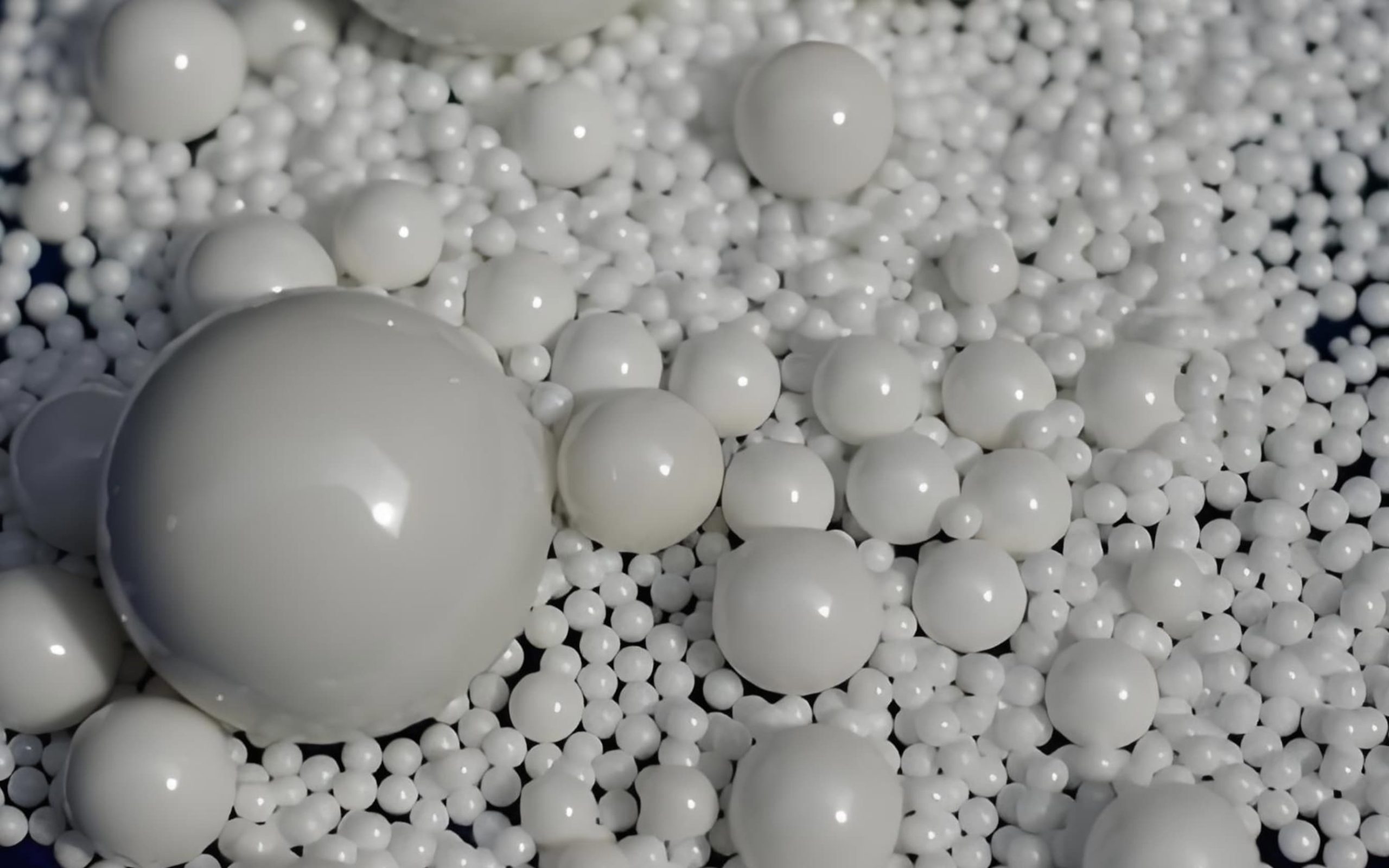
Ceramic spheres make contact with the workpiece at a single point — the geometry that minimizes contact pressure for any given applied force. This point contact makes spheres the gentlest cutting action available among ceramic finishing media, producing a smooth, isotropic surface texture without the directional scratch patterns that flat-faced media can create.
Spheres are specified for final-stage polishing after aggressive deburring, finishing of delicate thin-wall parts where dimensional change must be minimized, and surface conditioning prior to plating or decorative coating. They are also the media of choice for non-abrasive “burnishing” operations, where porcelain (non-abrasive) spheres are used with a burnishing compound to cold-work the surface of steel parts, creating a bright, compressively stressed surface layer.
Spheres have the lowest lodging risk of any shape: they can enter a bore only if the bore diameter significantly exceeds the sphere diameter, and even then, a sphere cannot wedge — it will roll freely and exit under the influence of the machine’s vibratory motion. This makes spheres the safe default choice for parts with through-holes or bores at any angle.
The angle-cut cylinder sits between the straight cylinder and the diagonal cylinder in terms of recess access, while maintaining good flat-surface cut rate. Both ends are cut at a shallow angle (typically 15–25°), giving the chip a wedge-like profile that can partially enter shallow grooves and chamfers without the full penetration of a diagonal cut. This geometry is particularly effective for parts with chamfered edges, shallow counterbores, and gentle undercuts that require more access than a straight cylinder can provide, but less point-contact reach than a cone.
Angle-cut cylinders are frequently used as a single-shape solution for mixed-geometry batches where a variety of part types — some flat-dominant, some with light recesses — are processed together. Their versatility reduces the need for process changeovers, simplifying operations in job-shop environments with high product mix and low batch volumes per part number.
3. Shape × Application Decision Matrix
The matrix below maps each ceramic media shape against nine common application scenarios. Use it as a rapid first-pass filter before cross-referencing the individual shape profiles above for detailed guidance. ● = Best choice, ◐ = Acceptable, ○ = Not recommended.
| Application | Triangle | Cylinder | Diagonal Cyl. | Cone / Tri-Star | Sphere | Angle-Cut |
|---|---|---|---|---|---|---|
| Heavy burr removal (cast / forged) | ● | ◐ | ◐ | ○ | ○ | ◐ |
| CNC machining burrs (flat faces) | ● | ● | ◐ | ○ | ○ | ◐ |
| Gear / spline tooth root | ○ | ○ | ◐ | ● | ○ | ○ |
| Deep internal groove / slot | ○ | ○ | ● | ● | ○ | ◐ |
| Cross-bore / intersecting holes | ○ | ◐ | ● | ● | ○ | ◐ |
| Thin-wall stampings (delicate) | ○ | ◐ | ◐ | ◐ | ● | ◐ |
| Pre-plate / pre-coat surface prep | ◐ | ◐ | ◐ | ◐ | ● | ◐ |
| Cylindrical / turned components | ◐ | ● | ◐ | ○ | ○ | ● |
| Mixed geometry batch (job shop) | ◐ | ◐ | ◐ | ○ | ○ | ● |
4. Size Selection: The Numbers That Matter
Once shape is determined, size selection involves balancing three competing requirements: the media must be large enough to prevent lodging in part features, small enough to reach the areas needing treatment, and at a size that produces the desired final surface finish. Smaller media creates more bead-workpiece contact points per unit volume, enabling finer finishes but requiring longer cycle times to achieve the same total stock removal.
A key relationship that is often underappreciated: in vibratory finishing, the ratio of media size to bowl amplitude matters. When media chips are larger relative to the vibratory amplitude, the motion of the mass becomes more sluggish and the media-part contact frequency drops. Most vibratory machines are optimized for media in the 10–30 mm range. Using 50 mm chips in a machine designed for 15 mm chips will produce disappointing results even if the shape and grade are correct.
5. Lodging Prevention: The Complete Rule Set
Media lodging is the single most disruptive failure mode in mass finishing. A lodged chip must be detected (often not immediately obvious), the affected part must be removed from the batch, and the chip must be extracted manually — sometimes requiring a drill press, press tools, or even scrapping the part if the lodged chip has caused surface damage in the extraction attempt. Prevention is always cheaper than remediation.
Apply this formula to every opening, slot, groove, and pocket in the part — not just the most obvious ones. The “critical opening” is the largest dimension that a chip could align to during tumbling. For a rectangular slot 8 mm × 20 mm, the critical opening is 20 mm. For a 12 mm round bore, it is 12 mm. A media chip whose smallest dimension is 25 mm (1.25 × 20 mm) cannot enter the slot regardless of orientation. Add extra safety margin (×1.4 or ×1.5) for blind holes where chips cannot fall out under gravity.
Beyond the basic size rule, three additional practices significantly reduce lodging risk in production environments:
- Screen media regularly: Worn chips that have reduced to below the critical size must be screened out of the bowl charge. A media load that started at the correct size may develop undersized chips through normal wear. Run a periodic size-check screen (at minimum, monthly for continuous production) and remove fines.
- Use media stops for unavoidable conflict features: Where a part has both a feature that must be accessed (e.g., an external burr) and a feature that cannot be entered (e.g., a precision bore), use silicone or rubber media stops — plugs inserted into the bore before loading. They prevent media entry while leaving all external surfaces accessible.
- Verify with a first-article inspection: Before running a full production batch of a new part number, run a single-part trial with the specified media. Inspect the part thoroughly after the trial cycle, paying specific attention to every hole, slot, and recess. Only after confirming zero lodging should the full batch be committed to the process.
6. Two-Stage & Mixed-Media Strategies
When no single ceramic media shape can serve all finishing requirements of a part simultaneously — because the part has both features requiring aggressive cutting and features requiring delicate access — a two-stage or mixed-media strategy resolves the conflict. These approaches add handling complexity but routinely deliver surface finish results impossible to achieve in a single operation.
Two-Stage Sequential Processing
Stage 1 uses a large, aggressive shape (typically a triangle or straight cylinder in a heavy-cut grade) to remove the bulk of the burr material from all accessible surfaces. Stage 2 uses a smaller, lighter-cut shape (diagonal cylinder, cone, or fine-grade cylinder) to access recessed features and refine the overall surface finish. Between stages, parts are separated from the stage-1 media, rinsed, and loaded into the stage-2 machine. Total processing time increases by 30–60% compared to a single-stage process, but the achievable finish quality improves dramatically.
Two-stage processing is standard in aerospace turbine blade manufacturing, surgical instrument finishing, and any application where both heavy burr removal and fine surface conditioning are specified on the same part drawing.
Mixed-Media Single-Load Processing
An alternative to two-stage processing is loading a mixture of two different chip sizes (typically a 3:1 or 4:1 size ratio) in the same vibratory bowl simultaneously. The large chips handle primary burr removal on accessible surfaces, while the small chips migrate into recesses and provide finer finishing action. This approach works well for parts with relatively shallow recesses (depth-to-opening ratio below 1:1). For deep recesses, the separation between large and small chips in the bowl under vibratory motion limits the effectiveness of the small chips in the target area.
A practical guideline for mixed-media ratio: Load the larger media at 70–75% of total media volume and the smaller media at 25–30%. This ratio maintains adequate bowl flow dynamics — too much small media reduces the mass-transfer efficiency of the larger chips, while too little small media provides insufficient coverage of the target recessed features.
7. Workpiece Geometry Mapping
The following table consolidates the shape selection guidance into a rapid lookup reference organized by workpiece geometry type. Use your part drawing to identify the dominant geometry category, then apply the recommendations as a starting specification for trial validation.
| Workpiece Geometry Type | Primary Shape | Secondary Shape | Size Starting Point | Lodging Watch Point |
|---|---|---|---|---|
| Flat plate / sheet metal stamping | Triangle | Angle-cut cylinder | 10 – 15 mm | Any punched holes ≥ media size |
| Turned / cylindrical component | Straight cylinder | Angle-cut cylinder | 8 – 20 mm | Bores, cross-holes, internal threads |
| Prismatic machined block | Triangle | Diagonal cylinder | 10 – 20 mm | Pockets, tapped holes, slots |
| Die casting (complex geometry) | Diagonal cylinder | Cone / Tri-star | 8 – 15 mm | Draft-angle features, core pins |
| Investment casting | Diagonal cylinder | Triangle (initial scale) | 10 – 20 mm | Thin-wall sections, core holes |
| Gear / splined shaft | Cone / Tri-star | Cylinder | 6 – 12 mm (cone tip) | Tooth root depth vs. cone tip width |
| Forging / heavy burr | Triangle (large) | Cylinder | 20 – 40 mm | Draft angles, parting line pockets |
| Medical implant / delicate part | Sphere | Fine cylinder | 5 – 10 mm sphere | Any feature smaller than sphere dia. |
Selecting the correct combination of shape and size for your specific workpiece reduces trial iterations, accelerates process qualification, and minimizes scrap. For the full five-step selection process that integrates shape with abrasive grade, machine type, and compound selection, refer to our systematic How to Choose Ceramic Media guide. For an understanding of how ceramic tumbling media compares to plastic and steel alternatives for each workpiece type, see our Ceramic vs. Plastic vs. Steel Media comparison.
📄 Related: Ceramic Tumbling Media — Complete Mass Finishing Guide Machine types, cut rate tables, compound selection, and 6-step process setup framework8. Frequently Asked Questions
The triangle is the most widely used ceramic media shape for general industrial deburring, accounting for an estimated 45–50% of global mass finishing media consumption by volume. Its combination of high cut rate on flat surfaces and external edges, wide availability across all sizes and abrasive grades, and compatibility with all machine types makes it the default starting point for most new applications. The main limitation is lodging risk in slots and bores — applications with complex internal geometry require diagonal cylinders or cones instead.
The clearest indicator is finding chips lodged inside the part after processing. If even one chip lodges during a trial run, the media is too small for that part feature. Preventatively, apply the anti-lodging formula: the smallest dimension of the chip must be at least 1.25 times the largest critical opening in the part. Also inspect parts for chips that entered a hole or bore but exited — the interior of the feature may show unintended abrasion or witness marks, indicating that smaller chips are accessing areas where they should not be.
The same shape can be used across machine types, but the optimal size and bond hardness will differ. Centrifugal barrel machines generate 5–25 times the G-force of vibratory machines, which means chips experience much higher impact forces per contact event. In a centrifugal barrel, use a smaller chip size (to reduce impact energy per chip-to-part contact) and a harder bond formulation (to resist chipping under high-energy impact). Triangles used in vibratory machines in a medium-hard bond can fracture at their sharp ridges in a centrifugal barrel — specify a hard bond or rounded-ridge variant for CBF applications.
Yes. Jiangsu Henglihong Technology Co., Ltd. manufactures ceramic finishing media in all standard shapes across a full dimensional range, and offers custom tooling for non-standard shapes, modified dimensions, and specialized geometries designed for specific part families. Custom orders typically require a minimum quantity and a lead time of 4–8 weeks for tooling fabrication and first-article approval. Contact our engineering team with your part drawing and finishing specification to discuss custom media options.
Not Sure Which Shape Is Right for Your Part?
Send us your part drawing and finishing specification. Our engineering team at Jiangsu Henglihong Technology Co., Ltd. will recommend the optimal shape, size, and abrasive grade — and provide trial samples at no cost.
Get a Free Shape Recommendation →Filters