Masking and Fixturing for Abrasive Blasting Complex Titanium SLM Geometries
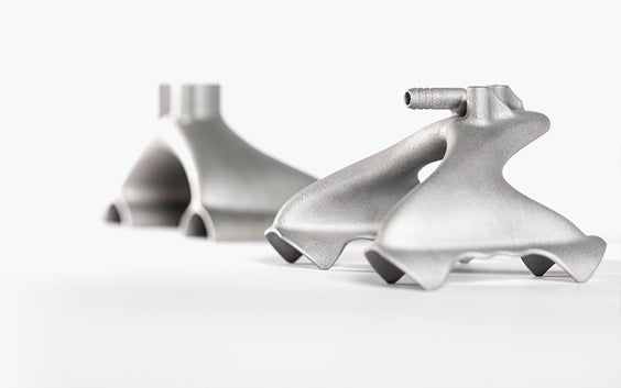
The geometric freedom that makes SLM valuable — internal lattices, conformal channels, undercuts, precision bores — is also what makes abrasive finishing more challenging than for machined components. Standard blast cabinets cannot uniformly treat an SLM part with internal cooling channels, precision bearing seats, and delicate lattice struts without a well-designed masking and fixturing plan. This guide covers which surfaces must be protected, what masking materials work on titanium, how to design repeatable fixtures, and how to blast internal features that directional nozzles cannot reach.
1. Features That Always Require Masking on Titanium SLM Parts
The starting point for any masking plan is identifying every surface that must not be blasted. On titanium SLM parts, this list is longer and more varied than on conventional machined components because SLM enables features — internal structures, organic profiles, simultaneous toleranced and non-toleranced surfaces on the same part — that machining produces separately and controls independently. This article is part of the series on abrasive finishing for titanium SLM parts.
Features that must always be masked before blasting titanium SLM parts:
- Precision bores, bearing seats, and pin holes: abrasive blasting roughens these surfaces beyond functional tolerance within seconds at typical blast pressures. A 20 μm Ra increase on a precision bore translates directly to a press-fit or clearance-fit failure.
- All threaded features: thread form geometry (flank angle, pitch, minor diameter) is degraded by media impact in one to three passes at production blast pressures. Internal threads require thread plugs; external threads require thread caps. Both must be installed before blasting begins and inspected for complete engagement before the part enters the blast cabinet.
- Sealing surfaces and O-ring grooves: surfaces that rely on controlled Ra for sealing function (metal face seals, O-ring contact surfaces) must be masked. Even a slight roughness increase on a face seal surface changes the sealing behavior and may require re-lapping.
- Precision mating faces and datum surfaces: surfaces used for fixture location in downstream operations (machining datums, assembly registration surfaces) must not be blasted because dimensional and form changes affect the accuracy of all subsequent operations.
- Optical surfaces, sensor windows, and wire pass-throughs: any surface with a different functional requirement from the blast target must be identified and masked.
2. Masking Materials: Selection and Titanium Compatibility
Silicone and EPDM rubber plugs: The standard solution for cylindrical precision holes. Silicone is preferred for titanium applications because it is chemically inert, does not deposit iron or reactive compounds on the titanium surface, and remains dimensionally stable across the temperature range of blast operations. EPDM is acceptable where temperature cycling above 150°C is not involved. Plugs must be precision-sized to fit snugly without being forced — a plug that requires excessive force may deform the bore if the titanium wall is thin. Color-code plugs by size for rapid installation verification.
Aluminum thread plugs and caps: For internal threads, precision-fit aluminum plugs protect the thread form. Aluminum is preferred over steel in titanium blasting operations because aluminum contamination of titanium is less harmful than iron contamination, and because aluminum plugs can be verified as clean by visual inspection. Use thread gauges to confirm that plugs achieve the required engagement before blasting. For external threads, aluminum caps or PEEK polymer caps (for applications where even aluminum contamination is unacceptable) provide thread protection.
Blast-grade vinyl masking tape: Reinforced vinyl tape (0.25–0.35 mm thick with a carrier film) handles flat or gently curved surfaces at blast pressures up to 60–80 PSI, depending on media type and blast angle. For angular media at high pressure, additional tape build-up at edges (2–3 layers) prevents media undercutting and edge lifting. Blast tape does not provide complete protection at HVOF-preparation pressures (70–90 PSI) — at these levels, use machined aluminum fixtures instead.
Custom-machined aluminum fixtures: For complex parts requiring repeatable, operator-independent masking of multiple features simultaneously, CNC-machined aluminum frames are the highest-reliability solution. The fixture clamps to datum features on the titanium SLM part (defined in the fixture design drawing) and simultaneously covers all critical surfaces with defined, controlled geometry. The fixture-to-part contact surfaces should be lined with silicone or PTFE sheet to prevent aluminum transfer to the titanium. Fixture-based masking enables the validated, documented processes required for ISO 13485 and AS9100 special process qualification.
3. Custom Fixture Design for Repeatable Masking
A well-designed blast fixture achieves three objectives simultaneously: it holds the part in the correct orientation relative to the blast nozzle, it protects all surfaces that must not be blasted, and it is reproducible — any operator installs it the same way every time, producing the same masking result. Fixtures that rely on operator judgment for positioning or sealing are a process control liability.
Fixture design principles for titanium SLM blasting:
- Clamp to defined datum features: the fixture locates on the same surfaces used for machining and inspection datums, ensuring consistent part orientation.
- Mask by contact, not by air gap: masking surfaces should contact the part surface to be protected, with a compliant silicone gasket providing the seal. Air-gap masking (the fixture is close but not in contact) allows media to enter and damage the protected surface.
- Design for one-handed operation: the operator must be able to install and remove the fixture with one hand while holding the part or blast gun, without needing a third hand to tighten fasteners. Cam-lever clamps, quarter-turn fasteners, and spring-loaded locating pins all enable one-handed fixturing.
- Document every fixture: assign a unique fixture identifier, maintain a drawing that shows the part number(s) it serves, the datum features it clamps to, the surfaces it protects, and the installation procedure. This documentation is required for AS9100 and ISO 13485 special process control.
4. Reaching Internal Channels and Lattice Structures
Directional dry blast cannot reach internal surfaces without line-of-sight access from the nozzle. For titanium SLM parts with internal cooling channels, lattice infill, or other inaccessible surfaces, two approaches are used:
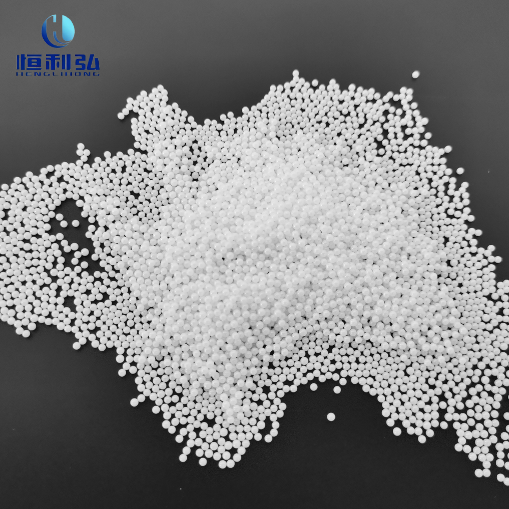
Wet blast with internal slurry flow: For parts with defined through-channels (inlet and outlet ports), a wet blast slurry is pumped through the channel under controlled flow rate and pressure. Media particles entrained in the slurry abrade the channel wall as they flow through, achieving Ra reduction on internal surfaces. A representative protocol: mesh 150–220 zirconia or glass beads in 20–30% v/v slurry, pumped at 0.5–1.5 L/min through the channel at 20–40 PSI inlet pressure, for 5–10 minutes per channel segment. Coverage uniformity depends on channel diameter (larger channels allow more turbulent flow and better coverage), channel length (shorter channels blast more uniformly), and flow rate (higher flow rate improves coverage in long channels). Blind channels with no outlet port cannot be treated by this method.
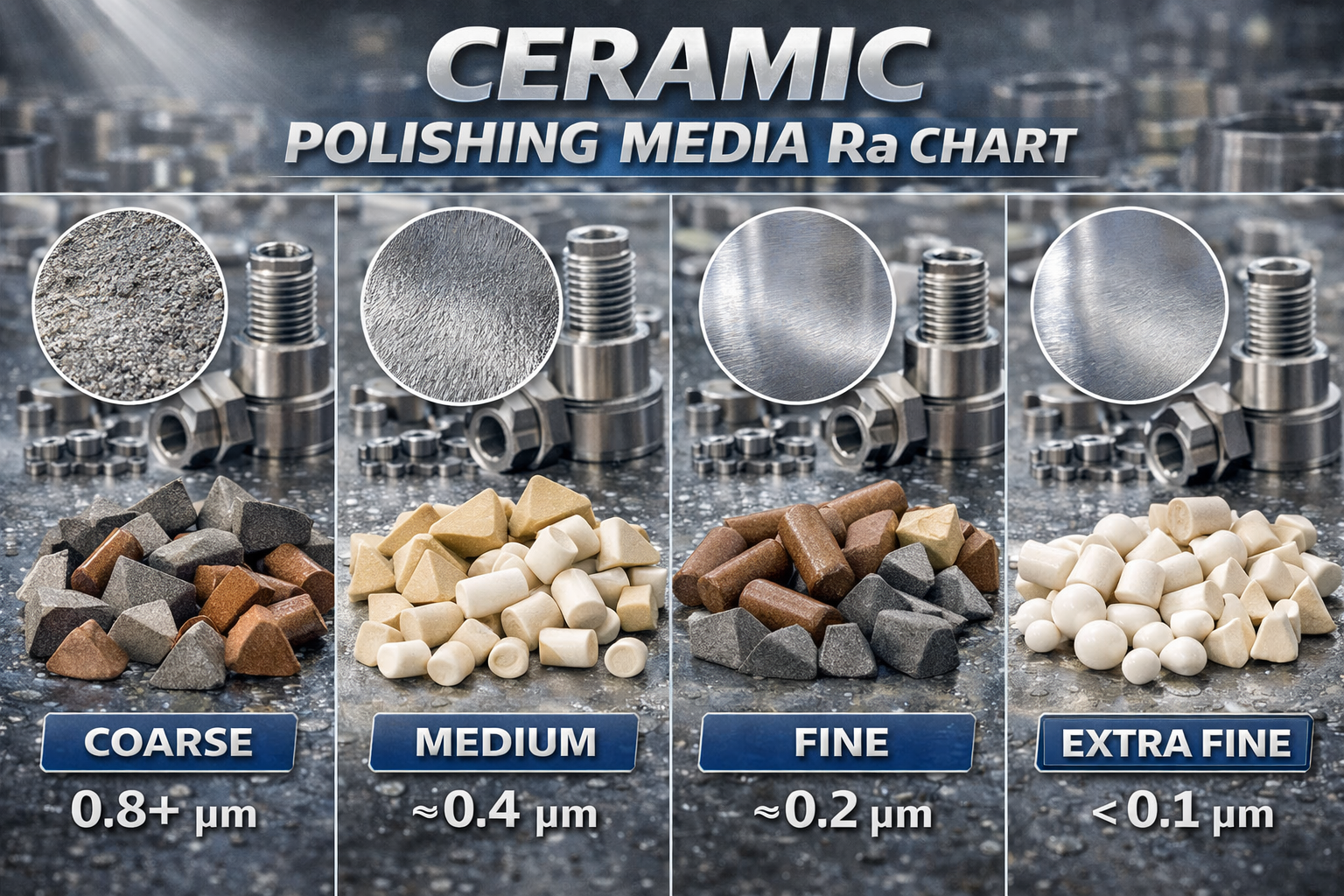
Vibratory finishing: For lattice structures with open-cell geometry (cell openings 0.5–1.5 mm), fine ceramic chip media (2–5 mm length, 8 Mohs hardness) in a vibrating bowl contacts internal strut surfaces as the media tumbles through the open lattice. Process: 30–60 minutes at 50–60 Hz vibration frequency, with media-to-part weight ratio approximately 10:1. Ra reduction from the as-built range (5–18 μm) to approximately 1.5–4 μm is achievable on lattice strut surfaces accessible to the chip media. Fully enclosed lattice volumes (no through-path for media) cannot be processed by vibratory finishing.
Internal lattice finishing is particularly important for titanium SLM orthopedic implants. For implant-specific surface requirements, see our guide on abrasive finishing titanium SLM orthopedic implants: Ra targets, contamination control, and ISO 13485.
5. Documentation for Regulated Applications
For aerospace (AS9100) and medical device (ISO 13485) applications, masking is a controlled process step that must be documented, qualified, and verified. The documentation package for a masking operation includes: a masking drawing or instruction (specifying which surfaces are masked, which masking materials are used, and how masking is installed and verified); the masking installation record (operator ID, date, time, fixture identification, verification sign-off); and the post-blast masking removal record (confirming all masking was removed, with no retained masking debris on the part). For first-article qualification, the masking plan is reviewed by engineering and quality before production blasting begins. Masking changes — new materials, fixture modifications, new part numbers — require a documented change control process.
6. Common Masking Failures and How to Prevent Them
The most common masking failures in titanium SLM blasting operations and their root causes:
- Thread plug not fully engaged: a plug installed at less than the required thread engagement allows media to enter and damage thread flanks near the mouth of the hole. Prevention: define minimum engagement depth on the masking instruction and verify by mark or gauge before blasting.
- Tape edge lifting at high pressure: blast media entering under the tape edge roughens the protected surface. Prevention: use additional tape build-up at all edges, use higher-adhesion blast-grade tape, or replace tape masking with aluminum fixtures for pressures above 60 PSI.
- Forgotten masking items: in a complex masking operation with 15–20 individual plugs and tape areas, the most common failure is a single plug or tape piece omitted. Prevention: use a sequential masking checklist tied to the masking drawing, with mandatory check-off for each item, and a final “all masking installed” sign-off before the part enters the blast cabinet.
- Masking retained after blasting: retained masking materials (particularly tape adhesive residue) contaminate the blasted surface and may affect downstream processing. Prevention: include masking removal and verification as explicit steps in the work order, with photographic evidence for regulated applications.
Frequently Asked Questions
Use precision-fit thread plugs made from aluminum or PEEK polymer (depending on contamination requirements). The plug must engage a minimum of 3–5 full thread pitches to provide effective protection — too shallow and media enters around the plug perimeter and damages the first threads. For blind holes, ensure the plug does not bottom out before achieving adequate thread engagement. Color-code plugs by thread size and pitch to prevent mix-ups. For medical applications, use aluminum (not steel) plugs to avoid iron contamination, and verify each plug is removed and accounted for after blasting using a count-in/count-out system documented on the masking checklist.
Standard blast-grade vinyl tape (reinforced carrier, 0.25–0.35 mm thick) provides reliable protection at pressures up to 60 PSI with coarse angular media (Al₂O₃ grit 60–80) and up to 80 PSI with fine spherical media (glass beads mesh 150–200). Above these limits, media energy is sufficient to abrade through the tape or lift tape edges, allowing media ingress to the protected surface. For HVOF anchor profile blasting at 70–90 PSI with coarse grit, tape masking is not adequate — use aluminum-machined fixtures with silicone gaskets. Always perform a tape adhesion test on the specific titanium SLM surface material before production use, as titanium surface energy affects tape adhesion.
Yes, indirectly. Build orientation determines which surfaces are upskin (cleaner, lower satellite density), downskin (rougher, higher satellite density), and vertical, which affects the blast protocol needed for each surface. It also determines the location of support structure attachment points — if supports were attached to precision surfaces (not recommended in good AM design practice but sometimes unavoidable), the support-attachment scars may require masking to prevent over-blasting while the surrounding surface receives the correct blast. Review the build orientation documentation alongside the masking drawing to ensure all support attachment scars are identified and their finishing treatment specified.
Putty-type masking compounds (silicone or polyurethane putty) are used in automotive and aerospace painting as temporary masks for irregular surfaces, and they are applicable to abrasive blasting for irregular features that tape or rigid fixtures cannot adequately cover. For titanium applications, use only silicone-based putty (no sulfur or phosphorus curing agents, which can contaminate titanium surfaces and affect oxidation behavior). Apply in sufficient thickness (minimum 3–5 mm) to provide adequate kinetic energy absorption at the blast pressure used. Verify that all putty is removed after blasting — putty residue left in recesses or blind features is a contamination source. Putty masking is not repeatable enough for AS9100/ISO 13485 controlled processes; use it for development work only, and replace with fixture-based masking for production.
Need Specialist Abrasive Media for Titanium SLM Finishing?
Jiangsu Henglihong Technology Co., Ltd. can advise on abrasive media selection for titanium SLM blasting operations where masking constraints limit accessible blast angles or require reduced pressures for thin-wall or lattice features. Contact our technical team for process-specific media and parameter recommendations.
Contact Our Technical TeamFilters