Abrasive Finishing for Titanium SLM Parts: Complete Guide to Surface Treatment, Media Selection, and Quality Control
Selective laser melting (SLM) has given engineers unprecedented design freedom with titanium — patient-specific orthopedic implants, topology-optimized aerospace brackets, and biomorphic lattice structures that no conventional process could produce. But freedom comes with a surface quality challenge. As-built SLM titanium surfaces carry Ra values of 5–20 μm, brittle oxidation layers, and partially fused satellite particles that standard blasting protocols are not designed to handle. This guide builds the complete technical framework for abrasive finishing of titanium SLM parts: how to identify each defect type, which media to select and why, how to adapt the process for aerospace, medical, and coating applications, and how to close the loop with the measurement and inspection protocols that regulated industries require.
1. Why Titanium SLM Parts Demand a Different Finishing Approach
1.1 The Metallurgical Context
Titanium alloys, and Ti-6Al-4V (Grade 5) in particular, present a combination of properties that defines every downstream finishing decision. The alloy delivers 1,000+ MPa yield strength at a density of just 4.43 g/cm³, excellent fatigue performance, and outstanding corrosion resistance — precisely the properties that make it the material of choice for load-bearing aerospace structures and long-term biomedical implants. But titanium is also intensely reactive at elevated temperatures. Above approximately 400 °C it begins absorbing oxygen and nitrogen from its environment; above 600 °C this absorption proceeds rapidly, creating a brittle oxygen-enriched surface layer that degrades fatigue life, reduces ductility, and can cause premature in-service failure.
In SLM, the melt pool routinely exceeds 1,700 °C — well above the titanium β-transus of approximately 995 °C for Ti-6Al-4V — and the surrounding powder bed undergoes repeated thermal cycling as each successive layer is melted. Even in a tightly controlled inert-argon build chamber, this thermal history leaves distinct metallurgical signatures at the part surface: signatures that do not occur in wrought billets, castings, or machined components, and that require targeted abrasive finishing strategies to address.
1.2 How the SLM Process Creates Its Surface Fingerprint
Four interconnected surface conditions arise directly from the layer-by-layer build process, and each influences the finishing protocol in a fundamentally different way.
Layer-boundary geometry. Each melt pool solidifies as a slightly convex bead, and successive beads overlap to form the bulk of the part. Where a melt pool transitions between the fully melted interior and the unmolten powder at the perimeter, a rough scalloped boundary forms. These scallops are most pronounced on faces built at shallow angles to the build platform, where each successive layer’s outer edge is exposed rather than buried beneath subsequent material. The result is an inherently directional, periodic roughness profile unlike anything produced by subtractive machining.
Partially fused powder adhesion. Powder particles surrounding the melt pool absorb radiant and conductive heat from the melt track. At the right distance from the track centerline, this heat is sufficient to sinter particles to the solidified edge — not to melt them completely, but enough to create a metallurgical bond that survives routine cleaning. These “satellite particles” are particularly prevalent on downfacing and channel surfaces where the melt pool is supported by loose powder rather than solidified material.
Residual stress state. Rapid heating and cooling during SLM generates steep thermal gradients, producing residual stresses that are typically tensile at or near the part surface. Tensile residual stress is a direct fatigue life reducer: it adds to the mean stress during cyclic loading, effectively raising the stress ratio and depressing the high-cycle fatigue (HCF) limit. For aerospace-critical titanium components, this stress state must be reversed — or at minimum neutralized — through controlled abrasive finishing, heat treatment, or a combination of both.
Surface oxidation and alpha-case risk. Even in a well-purged chamber, residual oxygen and the extreme thermal conditions of SLM can create a surface layer enriched with interstitial oxygen and nitrogen — the so-called alpha-case. This brittle layer is visually indistinguishable from the underlying microstructure but can cause catastrophic fatigue failures if left unaddressed on fracture-critical components.
1.3 Why Standard Blasting Protocols Are Insufficient
Engineers familiar with blasting conventional titanium or stainless steel may assume their existing parameters translate directly to SLM parts. In practice, three systematic differences make this unreliable.
First, the surface condition is far more heterogeneous. As-built SLM surfaces are not simply “rougher” versions of machined surfaces — their topography is dominated by melt pool bead geometry, not tool marks. Curvature, directionality, and depth of surface features differ fundamentally, requiring recalibration of both media selection and blast parameters from the ground up.
Second, SLM geometry brings surfaces that are difficult or impossible to reach with conventional blast equipment: internal cooling channels, undercut lattice struts, deep cavities. These require either robotic nozzle manipulation or, more practically, wet blasting with controlled slurry flow to achieve uniform coverage.
Third, the contamination risk is asymmetric and consequential. Steel shot commonly used for industrial blasting leaves iron residue acceptable on steel components but catastrophic on titanium: it creates galvanic corrosion initiation sites and violates ISO 10993 trace-metal requirements for medical implants. A protocol that treats titanium the same as steel will fail compliance requirements and may cause field failures.
The following sections build a titanium-SLM-specific framework, addressing each of these challenges from defect identification through final inspection.
2. The Surface Defect Landscape Unique to Titanium SLM
Understanding the specific surface defects present on as-built SLM titanium is not an academic exercise — it directly determines the media type, blast pressure, and process sequence required. Attempting to blast a titanium SLM part without a clear defect map is analogous to sanding wood without reading the grain: you can damage the substrate while leaving the actual problem unresolved.
2.1 Alpha-Case: The Hidden Oxidation Layer
Of all the defects associated with titanium SLM parts, alpha-case is the most insidious. Unlike satellite particles or staircase roughness — visible at low magnification — alpha-case is metallographically invisible. It looks identical to the surrounding titanium matrix until the part is cross-sectioned, etched with Kroll’s reagent, and examined under optical or scanning electron microscopy at 200–500×. Yet it can reduce the fatigue life of a Ti-6Al-4V component by 50% or more, a consequence that has contributed to in-service aerospace failures where it was not adequately controlled.
Alpha-case forms when interstitial oxygen (and to a lesser extent nitrogen) diffuses into the hexagonal close-packed (HCP) α-titanium phase at elevated temperatures, stabilizing the α phase and creating an oxygen-enriched layer that is harder, more brittle, and more crack-prone than the base alloy. In the SLM build environment, primary sources include residual atmospheric oxygen in the build chamber — even at <0.1% O₂ levels, repeated layer-by-layer thermal cycling can develop alpha-case — contamination from previously processed reactive materials in shared chambers, and post-build handling in ambient air before the part has fully cooled below 400 °C.
Typical alpha-case depth on SLM titanium ranges from 10 μm in well-controlled machines with fresh argon to 150 μm or more in older systems with higher chamber oxygen content or in parts that were left exposed to air during slow cooling. ASTM F2924, which governs Ti-6Al-4V laser powder bed fusion, specifies that alpha-case inspection is required for fracture-critical applications, and many aerospace primes require destructive metallographic sampling from each build plate witness coupon to confirm depth before production parts are released.
Removing alpha-case by abrasive blasting requires a staged, media-progressive approach. Coarse aluminum oxide (grit 60–80) provides the aggressive cutting action needed to remove the enriched layer without excessive substrate loss, followed by a finer grit sequence (grit 120–180) to restore surface quality after the coarse stage and reduce the Ra introduced by the initial pass.
Deep dive: For a complete protocol covering alpha-case identification, depth estimation from build records, and the step-by-step blast removal and verification procedure, see our detailed article on alpha-case removal from SLM titanium parts using abrasive blasting.
2.2 Satellite Particles and Partially Sintered Powder
Satellite particles are small spherical or irregular metallic particles adhered to the surface of a larger, more fully sintered feature. They form because the powder surrounding the melt pool absorbs radiant and conductive heat from the melt track, and at the correct distance from the track centerline, this absorbed energy is sufficient to partially sinter particles to the solidified edge — not to fully melt them, but enough to create a metallurgical bond that survives basic cleaning operations such as compressed air blowing or ultrasonic washing.
Under scanning electron microscopy (SEM), satellites typically appear as spherical protrusions ranging 5–80 μm in diameter, sometimes carrying their own secondary satellites. Their distribution is not uniform: downfacing and side surfaces, where the melt pool transitions into unsupported powder, carry the highest satellite density. Horizontal upskin surfaces are typically cleaner because the powder above the final layer is simply removed during post-build depowdering.
In biomedical applications, satellite particles are a regulatory and clinical concern. Particles that detach in vivo can trigger adverse tissue responses, particulate disease, or embedding in bone — failure modes well documented in the clinical literature on early-generation metal-on-metal hip systems. For dental implants, surface particles compromise the precise Ra 1–4 μm micro-topography required for reliable osseointegration. In aerospace, particles act as stress concentration features and fatigue initiation sites under cyclic loading, where even a small surface inclusion can nucleate a crack in high-cycle fatigue conditions.
Removal requires a delicate approach: sufficient kinetic energy to dislodge the sintered bond without creating new embedded particles or peening the satellite material into the substrate. Fine aluminum oxide (mesh 150–200) or fine glass beads at controlled blast pressures of 30–50 PSI, with a standoff distance of 150–200 mm and a 60–75° nozzle angle, strikes this balance for most Ti-6Al-4V SLM builds.
Deep dive: See our technical guide on removing satellite particles and partially sintered powder from titanium SLM parts by abrasive blasting — covering SEM characterization, nozzle configuration, process parameters, and post-removal inspection verification methods.
2.3 The Staircase Effect and Layer-Line Roughness
Any layered manufacturing process produces a staircase-like approximation of curved or angled surfaces. In SLM, this staircasing arises because geometry is built in discrete layers — typically 30–60 μm thick for titanium — and any surface that departs from the vertical build direction will show stepped layer boundaries at a periodicity equal to the layer thickness.
The theoretical arithmetic mean roughness (Ra) of an untreated SLM surface can be estimated geometrically. For a surface built at angle θ from horizontal, the staircase height approximates the layer thickness t, and Ra_theoretical ≈ t × cos(θ) / (2 × sin(θ)). This means surfaces built at 30° to horizontal — common for self-supporting overhangs designed to avoid support structures — carry a theoretical Ra three to five times higher than surfaces built at 75°. In practice, measured Ra values on as-built SLM titanium range from approximately 5 μm on near-vertical walls to 20+ μm on shallow-angle downskin faces. Upward-facing top surfaces typically fall in the 4–8 μm range after powder removal.
This roughness is also strongly directional. Measured parallel to the build direction, Ra reflects the layer-by-layer staircase profile; measured perpendicular to the build direction, Ra reflects the melt track width and bead-to-bead spacing. A single 2D contact profilometer measurement therefore gives an incomplete — and potentially misleading — characterization of an SLM surface. Three-dimensional areal parameters from ISO 25178 (Sa, Sq, Sdr) are more representative, particularly when the part will be subject to fatigue loading or coating.
Abrasive finishing reduces staircase roughness by progressively blunting and eroding the stepped features, converting an anisotropic layered profile into a more uniform, randomly distributed topography. The process requires a graded media sequence — coarser grit to break down the high points of the staircase steps, finer media to achieve the final Ra target — with blast angle and dwell time calibrated separately for upskin, downskin, and vertical faces.
Deep dive: Our guide on reducing staircase effect and layer-line roughness on titanium SLM parts with abrasive finishing provides the complete media grading sequence, orientation-specific parameters, and measured Ra reduction benchmarks from as-built to finished specification.
3. Choosing the Right Abrasive Media for Titanium SLM Finishing
Media selection for titanium SLM finishing is not a simple “harder abrasive = faster cut” decision. Titanium’s reactivity, the precision of Ra targets in aerospace and medical applications, and strict contamination requirements demand a systematic approach that weighs cutting performance, contamination risk, media durability, and cost per part simultaneously.
3.1 The Three Primary Media Types: Properties and Trade-offs
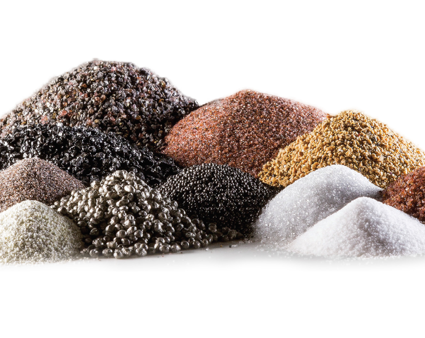
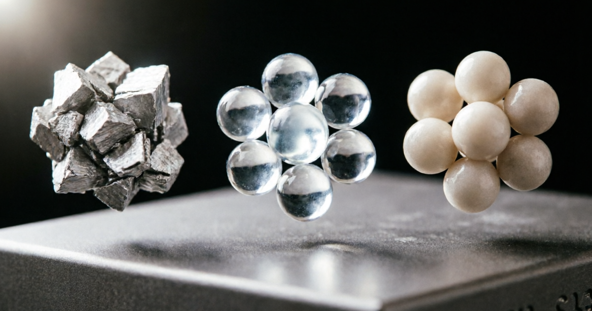
Aluminum oxide (Al₂O₃). The workhorse of industrial abrasive blasting, aluminum oxide carries a Mohs hardness of approximately 9.0 and an angular, blocky particle morphology that delivers efficient cutting action. For titanium SLM, Al₂O₃ is appropriate for aggressive material removal tasks: eliminating alpha-case layers, breaking down heavy staircase roughness, and creating anchor profiles for thermal spray coatings. Its principal limitations in titanium applications are two. First, angular Al₂O₃ particles can embed in the relatively soft titanium surface — particularly at higher blast pressures — leaving alumina inclusions detectable by XRF that are problematic for medical implant biocompatibility. Second, unless blast equipment is dedicated to titanium, Al₂O₃ media accumulates ferrous contamination from prior steel parts, which transfers to the titanium surface on the next cycle.
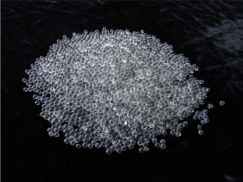
Glass beads (silica-based). Spherical glass beads — typically manufactured from soda-lime or borosilicate glass — provide a gentler, peening-dominated surface treatment. Their Mohs hardness of approximately 5.5 means material removal is slow, but the spherical impact geometry introduces compressive residual stress at the surface rather than cutting away material. For titanium SLM finishing where Ra targets are moderate (1.6–3.2 μm) and the objective is surface improvement without aggressive stock removal, glass beads are an effective and economical choice. Their limitations include a shorter recycling lifespan (typically 400–800 cycles before excessive breakdown to angular fragments) and trace iron and alkaline earth metals present in standard glass formulations. For medical-grade titanium, glass beads must be confirmed iron-free by XRF certification from the media supplier.
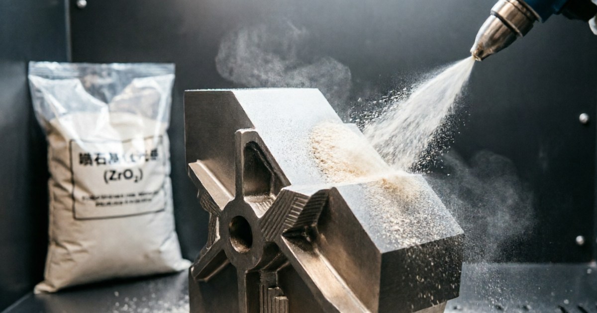
Zirconia beads (ZrO₂). Yttria-stabilized zirconia beads represent the premium option for titanium SLM finishing in regulated industries. With a Mohs hardness of approximately 8.5, zirconia provides effective material removal and compressive stress induction without the contamination risk of glass or the embedding tendency of angular Al₂O₃. Critically, zirconia is biocompatible and chemically inert, producing no iron or silica contamination even at high blast frequencies. Their significantly longer recycling lifespan — 2,000–4,000 cycles — reduces cost per part over time, partially offsetting their higher initial price. In medical implant and high-purity aerospace applications, zirconia beads are increasingly the media of choice and the recommendation supported by Jiangsu Henglihong Technology Co., Ltd. for regulated end uses.
| Paramètres | Oxyde d'aluminium | Perles de verre | Perles en zircone |
|---|---|---|---|
| Dureté Mohs | ~9.0 | ~5.5 | ~8.5 |
| Morphology | Angular, blocky | Spherical | Spherical |
| Material removal rate | Haut | Faible | Medium |
| Embedding risk (Ti) | Medium–High | Faible | Very low |
| Iron contamination risk | Medium (shared equipment) | Low–medium | Very low |
| Recycling cycles | 300–600 | 400–800 | 2,000–4,000 |
| Minimum achievable Ra | ~0.8 μm | ~0.4 μm | ~0.5 μm |
| Preferred applications | Aggressive removal, coating prep | Peening, finish blasting | Medical, aerospace, precision |
Deep dive: For a complete head-to-head evaluation including cost-per-part modeling, Ra outcome data, and an application-specific decision matrix, see our guide on aluminum oxide vs. glass beads vs. zirconia for abrasive finishing titanium SLM parts.
3.2 The Iron Contamination Problem: Why It Matters More for Titanium
In blasting operations that handle steel components, iron contamination is background noise — the substrate is iron-based, so iron traces from the media are inconsequential. When those same blast cabinets are applied to titanium, the contamination becomes a serious engineering, regulatory, and commercial risk on three fronts.
The electrochemical problem. Titanium and iron form a galvanic couple with a potential difference of approximately 0.6 V in seawater conditions. Iron particles embedded in or on a titanium surface create micro-galvanic cells in any moist environment, accelerating corrosion of the iron particle and potentially pitting the surrounding titanium oxide layer. For aerospace components operating in maritime or de-icing salt environments, this is an active and quantifiable service risk.
The biocompatibility problem. ISO 10993, the international standard governing the biological evaluation of medical devices, requires that implant surfaces be free from potentially harmful metal traces. Free iron on a titanium implant surface fails this requirement, can provoke aseptic inflammatory responses, jeopardizes osseointegration quality, and causes regulatory non-conformances during device market approval submissions.
The inspection and detection approach. The ferroxyl test — applying sodium ferricyanide solution to the cleaned, dried surface and observing for blue spot formation within 2 minutes — is the standard in-process check for free iron on titanium. XRF surface analysis provides quantitative elemental verification. Both test results should be documented and archived in the batch record as evidence of contamination control.
The prevention strategy. The most reliable approach combines three layers: media selection (zirconia or dedicated Al₂O₃ that has never contacted ferrous parts), dedicated blast equipment (cabinets reserved exclusively for titanium and non-ferrous alloys), and post-blast passivation with nitric acid to dissolve any residual surface iron that survives mechanical cleaning. Where shared equipment is unavoidable, a thorough wet-blast purge cycle with fresh media before processing titanium reduces — but does not eliminate — the contamination risk.
Deep dive: See our complete protocol on preventing iron and foreign material contamination when abrasive blasting titanium SLM parts — covering detection methods, equipment management, media certification, and passivation specifications.
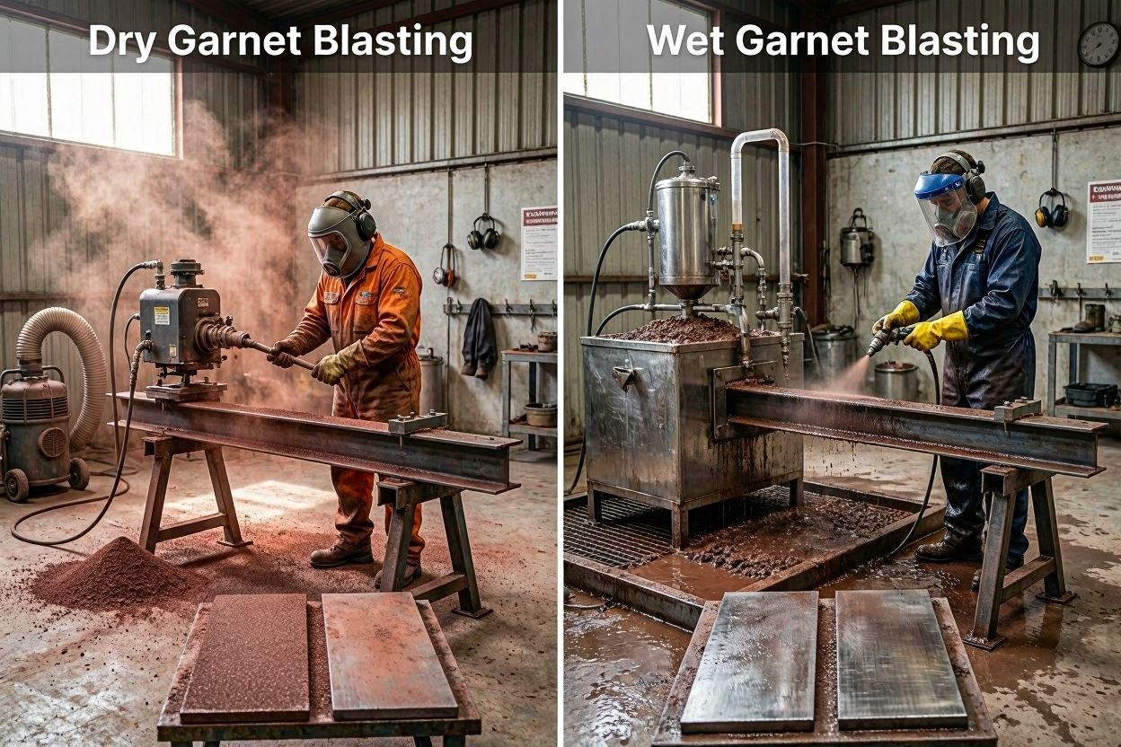
3.3 Wet Blasting vs. Dry Blasting: Matching the Process to the Application
The choice between wet (hydro) blasting and conventional dry blasting is primarily about how the carrier medium — air versus water-slurry — affects impact mechanics, surface outcome, and operational requirements. Both processes can use Al₂O₃, glass beads, or zirconia beads; the carrier medium is the key variable.
In wet blasting, media particles are suspended in a water-media slurry at concentrations of 10–30% by volume and propelled against the workpiece by compressed air through a specialized gun. The water film surrounding each particle dampens impact energy, reduces peak kinetic load, and provides a lubricating cushion that dramatically lowers the risk of media embedment in the titanium surface. The water also serves as a coolant — important given titanium’s reactivity at elevated temperatures — and continuously flushes debris from the surface, preventing re-embedding of dislodged satellite material.
Ra outcomes from wet blasting are generally finer at equivalent media size compared to dry blasting. A 120-mesh glass bead in a dry process might achieve Ra 0.8–1.2 μm on titanium; in a wet process at equivalent air pressure, the same media typically achieves Ra 0.4–0.8 μm, because the water film limits deep gouging of individual impact sites. This finer control makes wet blasting the preferred process for medical-grade titanium implant finishing, where Ra tolerance windows may be as narrow as ±0.5 μm.
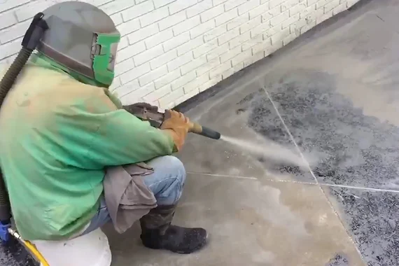
Dry blasting, by contrast, offers higher throughput, simpler equipment, and better accommodation of coarse angular media required for heavy stock removal, alpha-case elimination, and HVOF thermal spray anchor profile creation. Dry blast cabinets are more ubiquitous in industrial settings and easier to integrate into high-volume production lines.
The practical guidance: use wet blasting for medical implants, precision aerospace surfaces with tight Ra tolerances, and any application where media embedment compromises surface integrity. Use dry blasting for industrial applications, aggressive material removal tasks, and coating preparation. For operations handling both work types, maintaining a wet blast machine alongside a dry cabinet covers the full application range with the right process for each.
Deep dive: Our full process comparison on wet blasting vs. dry blasting titanium SLM parts covers equipment requirements, side-by-side Ra outcome data, operating cost comparisons, and decision criteria for each application type.
4. Finishing Protocols by Industry Application
The Ra target, contamination requirement, and regulatory framework differ substantially between titanium SLM end-use scenarios. This section outlines the finishing approach for the four major application categories, each with its own surface specification and compliance context.
4.1 Orthopedic and Dental Implants: Precision Surface Engineering for Osseointegration
Titanium has been the dominant material for orthopedic implants since the 1960s, and as of August 2026 a growing proportion of patient-specific spinal fusion cages, hip stems, tibial trays, and dental root-form implants are produced by SLM. The combination of controlled porosity for bone ingrowth, patient-specific fit, and the ability to produce complex internal lattice structures has made SLM the preferred method for many orthopedic applications where customization improves clinical outcomes.
The biological rationale for surface roughness control on titanium implants is well established. In vitro and in vivo studies consistently show that osteoblast attachment, proliferation, and differentiation are promoted by surface Ra in the range of 1–4 μm, where micro-scale roughness provides mechanical interlocking sites for the extracellular matrix and guides cell alignment. Surfaces smoother than Ra 0.5 μm reduce initial cell adhesion; surfaces rougher than Ra 6 μm can impair direct bone-implant contact quality by leaving gaps that fibrous tissue fills instead of bone.
For dental implants, the SLA (Sand-blasted, Large grit, Acid-etched) surface treatment process remains the clinical gold standard. SLA surfaces are created by blasting with coarse Al₂O₃ or TiO₂ grit to create macroroughness (Ra 2–4 μm), followed by chemical etching in a mixed hydrochloric/sulfuric acid solution to add microroughness at the 1–3 μm scale. When applied to SLM titanium implants, the blasting step must be calibrated against the as-built SLM Ra baseline — which is already significantly higher than a machined blank — to avoid over-blasting and creating a surface profile that falls outside the osseointegration window.
For orthopedic components with internal lattice structures — increasingly common in tibial trays, vertebral cages, and acetabular cups — abrasive finishing must penetrate the lattice interior uniformly. This places constraints on bead diameter (typically 50–150 μm bead size to enter lattice cells of 500–1,200 μm), blast pressure (excessive pressure deforms thin lattice struts), and process dwell time (extended dwell allows media to cycle through internal spaces). Wet blasting is preferred for lattice-bearing implants because the slurry can be flowed through internal channels under controlled pressure, achieving coverage that directional dry blasting cannot reach.
From a regulatory standpoint, the finishing process for implantable titanium devices must be validated as a special process under ISO 13485. Installation qualification (IQ) documents that the equipment is correctly installed and calibrated; operational qualification (OQ) demonstrates that the defined process parameters consistently produce outputs within specification; performance qualification (PQ) proves that the validated process reliably and repeatably produces finished parts that meet the acceptance criteria across multiple production runs. Blast media traceability, batch records, contamination test results, and Ra measurement reports form the QC package that accompanies each finished part number through the device file.
Deep dive: Our complete guide on abrasive finishing titanium SLM orthopedic implants — Ra targets, contamination control, and ISO 13485 compliance provides the validated process framework, contamination protocols, and QC documentation structure for compliant implant production.
4.2 Aerospace Components: Shot Peening, Fatigue Life, and NADCAP Compliance
For aerospace structural titanium SLM components — engine brackets, turbine blade attachments, airframe fittings, actuator hardware, and heat exchanger manifolds — the finishing objective is not simply surface smoothness. It is fatigue life. And the dominant mechanism linking abrasive finishing to fatigue life is the introduction of compressive residual stress (CRS) through shot peening.
The SLM build process leaves tensile residual stress at or near the titanium surface, arising from the steep thermal gradients and rapid solidification inherent to the process. Tensile surface stress raises the effective mean stress during cyclic loading, shifting the material’s position on a Goodman diagram unfavorably — reducing the allowable stress amplitude for a given HCF life requirement. For Ti-6Al-4V, which is used extensively in fatigue-critical aerospace structures, this built-in tensile stress state can reduce the HCF limit by 20–40% compared to an equivalent wrought microstructure. For primary structure and engine components, this deficit is unacceptable.
Shot peening addresses this directly. Bombarding the surface with high-velocity spherical media plastically deforms the surface layers, inducing compressive residual stresses that typically extend 0.1–0.5 mm into Ti-6Al-4V. This compressive zone must be overcome by the applied tensile loading before surface fatigue cracks can nucleate and grow — effectively raising the HCF limit back toward (and in some cases above) the wrought baseline. X-ray diffraction (XRD) measurement of the residual stress depth profile is used in development and periodic auditing to confirm that the CRS layer meets the design requirement.
The peening process for aerospace titanium SLM is governed by AMS 2430 (Shot Peening, Computer Controlled). This standard specifies:
- Almen intensity: the peening intensity, measured by deflection of calibrated steel strips (type A, C, or N) attached to a standard block. For Ti-6Al-4V aerospace components, required intensities typically range from 6A to 18A depending on section thickness and the CRS depth requirement.
- Coverage: the percentage of the surface area showing evidence of peening impact. Full coverage (≥98%) is required for most structural titanium components; some low-criticality surfaces accept 100% at reduced intensity.
- Media specification: media must be within specified hardness and size range, free from broken particles (which create sharp impact features rather than smooth compressive dimples), and free from contamination.
- Process documentation: all peening parameters — intensity, coverage, machine settings, media batch, and Almen strip deflection results — must be documented, reviewed, and retained for the component’s traceability file.
NADCAP (National Aerospace and Defense Contractors Accreditation Program) accreditation for shot peening — specifically the AC7117 audit criteria — is required for most aerospace supply chains processing flight-critical components. NADCAP auditors verify not only that the process is documented but that equipment calibration is current, operators are trained and qualified, and process deviations are managed through an effective corrective action system.
For titanium SLM parts, steel shot presents an iron contamination risk. The preferred media for aerospace titanium peening is ceramic shot (typically ZrO₂-based or SiO₂-ZrO₂ blends) or conditioned glass beads of appropriate intensity grade (S110–S330). Where customer specification requires steel shot, thorough post-peening passivation per AMS 2700 is mandatory, and contamination verification by ferroxyl test and XRF is required before the part proceeds to subsequent operations.
Deep dive: Our technical guide on shot peening titanium SLM aerospace parts — AMS 2430, fatigue life improvement, and NADCAP compliance covers the full peening protocol, Almen strip setup, media selection by intensity grade, and the documentation trail required for first-article qualification and sustained production.
4.3 Pre-HIP Surface Preparation: The Often-Overlooked Step
Hot isostatic pressing (HIP) is increasingly applied to aerospace and premium industrial titanium SLM parts to eliminate internal porosity. In HIP, the component is subjected to inert gas pressure of 100–200 MPa and temperature of 895–955 °C simultaneously, driving diffusion bonding of internal pore walls and closing sub-surface voids that would otherwise act as fatigue crack initiation sites. For fracture-critical aerospace titanium SLM parts, HIP has become a de facto standard post-processing step at many primes.
The interaction between abrasive blasting and HIP is a topic that production engineers frequently underestimate. The concern is specific: if surface-connected pores are present on the as-built SLM part — pores that open to the external surface rather than being fully enclosed within the bulk — they can become sealed at their surface opening during HIP while the internal volume of the pore remains empty. The pressurizing argon gas cannot penetrate and collapse a sealed pore; instead, the pore is converted from an open surface defect to a sub-surface closed void filled with argon at residual pressure. These sealed argon-filled voids can expand during any subsequent high-temperature processing (laser welding, heat treatment above the solid solubility of argon in titanium) and appear as “HIP blisters” — localized surface bulging detectable by visual inspection, profilometry, or fluorescent penetrant inspection.
A carefully designed pre-HIP blasting step addresses this risk. The objective is not to heavily blast the surface but specifically to remove satellite particles and loosely bonded powder that are bridging pore openings — effectively clearing the mouth of surface-connected pores before HIP can seal them. Light blasting with fine Al₂O₃ (mesh 150–220) at low pressure (20–40 PSI) and short exposure time achieves this: it dislodges bridging particles without cold-working the surface enough to mechanically close the pore mouth, which would create exactly the problem we are trying to prevent.
Post-HIP, after internal porosity has been eliminated and the part has been thermally conditioned as needed, the final abrasive finishing sequence can be executed with parameters appropriate for the final surface specification. The pre-HIP blast is a process step in service of the HIP outcome; the final blast addresses the surface quality requirements for the component’s end use.
Deep dive: For the complete pre-HIP blast sequence, quality gate criteria, the interaction between blast parameters and HIP pore behavior, and post-HIP finishing recommendations, see our guide on pre-HIP abrasive surface preparation for titanium SLM parts.
4.4 Coating Preparation: PVD, DLC, and Thermal Spray Applications
Titanium SLM parts destined for physical vapor deposition (PVD), diamond-like carbon (DLC), or thermal spray coatings require surface preparation with a different primary objective from the biomedical or fatigue-life-focused protocols above. Here, the goals are cleanliness and anchor profile — creating a surface state that maximizes adhesion between the titanium substrate and the deposited coating.
Each coating technology demands a specific anchor profile range, and these ranges differ by an order of magnitude across coating types:
PVD coatings (TiN, TiAlN, CrN, AlCrN, and similar hard functional or decorative coatings) are deposited at 150–500 °C in vacuum, and adhesion depends on atomic-level bonding between the coating and substrate. The substrate Ra should be in the 0.4–1.6 μm range — smooth enough to prevent coating bridging over deep surface valleys, but not mirror-polished, which reduces the actual contact area. Surface cleanliness is paramount: any organic contamination, free iron, or residual media must be removed before the part enters the PVD chamber. Light Al₂O₃ (mesh 120–180) in a dry blast, followed by ultrasonic cleaning and passivation, is the typical preparation sequence. The interval between blasting and loading into the PVD chamber should not exceed 4–8 hours to prevent surface re-oxidation that would reduce coating adhesion.
DLC coatings are deposited by plasma-enhanced chemical vapor deposition (PECVD) and require a surface that is clean but also mechanically activated. Light blasting with fine media creates surface activation sites for the plasma process while providing a minimal Ra baseline (Ra 0.2–0.8 μm). DLC adhesion is highly sensitive to substrate preparation inconsistency; non-uniform blasting translates directly to variable coating adhesion and early delamination in service.
HVOF thermal spray (tungsten carbide-cobalt, MCrAlY, Inconel, and similar) relies primarily on mechanical interlocking between the sprayed lamellae and the substrate surface asperities. The anchor profile required is aggressive: Rz (mean maximum profile height) of 50–120 μm, equivalent to Ra approximately 6–12 μm. This requires coarse, angular Al₂O₃ (grit 20–60) at high blast pressure (65–90 PSI), creating a profile that HVOF lamellae can mechanically grip. The blasted surface must not be touched by bare hands or any contaminating surface between blasting and thermal spraying, and coating should begin within 8 hours of the blast operation to prevent titanium surface re-oxidation.
Plasma spray requirements are similar to HVOF, with Rz 40–100 μm typically sufficient. The slightly lower spray particle velocity of plasma compared to HVOF means slightly less anchor profile is needed, but the same preparation principles apply.
Deep dive: Our guide on surface preparation of titanium SLM parts for PVD, DLC, and thermal spray coatings covers anchor profile requirements and measurement, blast specifications for each coating technology, surface cleanliness standards, and the maximum coating interval after blasting.
5. Surface Roughness Measurement and Specifications
Surface roughness measurement on abrasively finished titanium SLM parts is more nuanced than on machined surfaces. As-blasted surfaces are isotropic — randomly distributed topography rather than directional tool marks — so measurement direction matters less but cut-off wavelength selection and parameter choice matter more. Complex SLM geometries also frequently cannot be accommodated by contact profilometers with straight-line stylus traversal, necessitating optical measurement methods.
5.1 Surface Parameters: Beyond Ra
The arithmetical mean roughness Ra is the most commonly specified parameter in engineering drawings and industry standards. It is also the least informative single descriptor for a blasted surface. Ra integrates all height deviations from the mean surface — positive peaks and negative valleys contribute equally — which means a surface with deep, narrow valleys and flat plateaus can report the same Ra as a surface with a rounded, uniform profile, yet the two surfaces behave completely differently under fatigue loading, coating adhesion, or tribological contact.
For titanium SLM finishing, the following parameters should be specified alongside Ra wherever the application justifies the measurement investment:
- Rz (mean maximum profile height): the average peak-to-valley height across five consecutive sampling lengths. Rz is more sensitive than Ra to individual extreme features — deep satellite craters, high peaks from media impacts — and better predicts coating behavior and fatigue crack initiation potential.
- Sa (arithmetical mean height, areal, ISO 25178): the 3D equivalent of Ra measured over a defined area rather than a single line. For complex SLM surfaces, Sa gives a more representative characterization than a single 2D profile scan that may miss local features.
- Sdr (developed interfacial area ratio): indicates how much the true 3D surface area exceeds the nominal projected area. A high Sdr indicates a topographically complex surface with high contact area — directly relevant for implant osseointegration and thermal spray coating adhesion.
5.2 Measurement Methods
Contact profilometry (stylus): the historical production standard. A diamond-tipped stylus traverses the surface at 0.75–1.0 mN to avoid scratching titanium, recording the height profile at sub-micron vertical resolution. Accurate for Ra, Rz, and profile parameters on flat or gently curved surfaces. Limitations: slow single-line trace, unable to measure steep slopes beyond ±60° from horizontal, and stylus tip radius limits lateral resolution for fine-scale features below ~2 μm.
Optical coherence scanning interferometry (CSI/VSI): non-contact, rapid, capable of measuring step heights from sub-nanometer to several millimeters, and able to characterize surface areas rather than single traces. Coherence scanning interferometers are the preferred instrument for areal Sa, Sdr, and Sz measurements on blasted titanium SLM surfaces, particularly for medical implant characterization where 3D surface parameters are increasingly required by regulatory bodies and purchasing specifications.
Confocal laser scanning microscopy: provides high lateral resolution (down to ~0.2 μm) and is frequently used in medical implant research to characterize SLA surfaces. Less common in production settings due to throughput constraints, but valuable for development work and specification correlation.
5.3 Industry Specification Targets
| Application | Ra Target | Rz (indicative) | Key Standard / Reference |
|---|---|---|---|
| Osseointegration — orthopedic / dental | 1–4 μm | 8–25 μm | ASTM F1875, ISO 10993 |
| Aerospace shot-peened structural | 1.6–3.2 μm | 10–20 μm | AMS 2430, MIL-S-13165 |
| PVD coating adhesion | 0.4–1.6 μm | 3–10 μm | Coating system specification |
| HVOF thermal spray anchor | 6–12 μm | Rz 50–120 μm | AWS C2.18, supplier spec |
| DLC coating preparation | 0.2–0.8 μm | 1.5–6 μm | PECVD equipment standard |
| Industrial structural — uncoated | 0.8–6.3 μm | 5–40 μm | ISO 1302, drawing callout |
| Plasma spray preparation | 4–10 μm | Rz 40–100 μm | Supplier / customer spec |
Deep dive: Our guide on surface roughness measurement for abrasively finished titanium SLM parts — Ra, Sa, and industry specifications covers instrument selection, ISO 25178 parameter interpretation, cut-off wavelength guidance, and the full specification matrix for each application type.
6. Masking and Fixturing for Complex Titanium SLM Geometries
The geometric freedom that makes SLM valuable — internal channels, conformal lattices, deep recesses, undercuts, precision bores — is also the engineering challenge that complicates abrasive finishing more for SLM parts than for machined components. Standard blast cabinets designed for simple prismatic or cylindrical workpieces cannot uniformly treat an SLM component with internal cooling channels, lattice infill, and precision engagement surfaces without careful masking and fixturing planning.
6.1 Features That Require Masking
Certain surfaces must be protected from the blast stream entirely. Precision bearing seats, bores, and pin holes are roughened beyond functional tolerances within seconds at typical blast pressures. Threaded features — both internal holes and external threads — are damaged by direct media impact; all must be plugged or capped. Sealing surfaces and O-ring grooves carry defined Ra requirements for sealing function and must not be altered. Mating faces with close-tolerance fits are affected because blasting removes 1–10 μm per pass and adds roughness, both of which compromise fit-up quality. Any optical surface, sensor window, or precision datum surface in the assembly must also be fully masked before blasting begins.
6.2 Masking Materials Compatible with Titanium
Silicone and EPDM rubber plugs are the standard for cylindrical holes. Precision rubber plugs seat snugly in the bore and provide reliable protection up to approximately 80 PSI. They must be dimensioned on a masking drawing and installed per a defined procedure to ensure consistent coverage.
Aluminum thread inserts and caps protect threaded holes. For blast equipment dedicated to titanium, aluminum plugs are preferred over steel (which introduces iron contamination risk). Thread plug installation should be documented on the work order traveler with torque or engagement depth specified.
Blast-grade vinyl masking tape (typically 0.25–0.35 mm thick with a reinforced carrier film) handles flat or gently curved surfaces up to approximately 60 PSI. Above this pressure or with coarse angular media, tape edges require additional build-up or rigid masking to prevent media undercutting.
Custom-machined aluminum fixtures are the highest-reliability solution for complex parts requiring repeatable, operator-independent masking of multiple features simultaneously. CNC-machined frames clamp to datum features on the part and simultaneously mask all critical surfaces with defined geometry. Although initial tooling cost is higher, fixture-based masking enables the validated, documented processes required under ISO 13485 and AS9100 for special process qualification.
6.3 Reaching Internal Channels and Lattice Structures
Internal channels and lattice structures present a fundamentally different access problem — the blast nozzle cannot see the surface to be finished. Two approaches address this: wet blasting with internal slurry flow (media entrained in slurry pumped through defined inlet and outlet ports, abrading the channel walls as it flows) for open-channel and through-hole features; and media tumbling or vibratory finishing with fine ceramic or plastic media for lattice structures with open-cell geometry accessible from the part exterior. For blind internal features with no through-access, chemical finishing (electropolishing or acid etching) is often the only practical option and falls outside the scope of abrasive blasting.
Deep dive: For detailed guidance on masking material selection, fixture design methodology, and internal channel and lattice finishing protocols for titanium SLM parts, see our dedicated guide on masking and fixturing for abrasive blasting complex titanium SLM geometries.
7. Post-Blast Cleaning, Passivation, and Inspection
The abrasive blasting operation is not the final step in the surface treatment workflow — it is the penultimate one. Post-blast cleaning, passivation, and inspection are essential to confirm that the finishing process achieved its objectives and to prepare the surface for downstream operations. Skipping or abbreviated these steps is one of the most common causes of downstream failures — coating delamination, contamination non-conformances, and failed final inspection — in titanium SLM finishing operations.
7.1 The Post-Blast Cleaning Sequence
Immediately after blasting, the titanium surface carries loose debris: dislodged satellite particles, fractured abrasive media fragments, metallic dust, and residual blast cabinet contamination. This debris must be removed before inspection or downstream processing or it will interfere with Ra measurement, transfer to coating equipment, provide particulate contamination sources in medical implant cleanrooms, and block the ferroxyl test from reading the actual titanium surface beneath.
The recommended cleaning sequence for abrasively finished titanium SLM parts:
Immediately after blasting, use clean dry compressed air (ISO 8573-1 Class 1 or 2 quality, oil-free) directed across the surface at 30–45° to dislodge and remove loose surface debris. Avoid perpendicular high-pressure air, which can re-embed particles in the blasted surface.
Immerse the part in a heated alkaline cleaning solution (sodium hydroxide-based or proprietary aerospace cleaner at 40–60 °C) in an ultrasonic cleaner for 10–20 minutes. Ultrasonic cavitation breaks the adhesion of fine embedded particles and removes organic contamination. Follow with multiple deionized (DI) water rinses to remove cleaning agent residues completely.
For applications where iron contamination is a concern, immerse the part in 20–40% v/v nitric acid (HNO₃) solution at room temperature for 30–60 minutes per AMS 2700 Method 1. This selectively dissolves free iron and other reactive metals from the titanium surface without attacking the underlying titanium oxide passive layer. Critically, avoid hydrofluoric acid for post-blast passivation — it is extremely hazardous and can cause inadvertent etching that alters the carefully established blast surface profile.
Rinse thoroughly with deionized water (resistivity ≥1 MΩ·cm) to prevent mineral deposits from tap water contaminating the surface. Dry with clean filtered nitrogen or in a clean oven at 60–80 °C. For medical implants, transfer directly to the cleanroom packaging area once dry.
7.2 Final Inspection Protocol
Contrôle visuel : under good lighting at minimum 10× magnification (ideally 30× stereomicroscope), verify a uniform matte finish with no pitting, no embedded media clusters, and no localized discoloration. Blue or gold iridescence on titanium indicates localized overheating during blasting — typically caused by excessive dwell time or insufficient standoff distance — and is a non-conformance requiring investigation.
Ferroxyl test: apply fresh sodium ferricyanide test solution to the cleaned and dried surface. Blue spot formation within 2 minutes indicates free iron. If positive after passivation, repeat the passivation step and re-inspect before releasing the part.
Ra measurement: use a calibrated contact profilometer or optical interferometer per the defined measurement protocol to confirm that the part meets the Ra specification at all designated measurement locations. Record measured values, measurement locations, instrument identification, and calibration certificate reference in the batch record.
Dimensional verification: if blasting has removed material from critical dimension zones (tolerance-bearing features), verify with calibrated gauging. In well-controlled titanium SLM blast processes, material removal per pass is typically 2–10 μm — rarely affecting even tight tolerances — but documentation is required for ISO 13485 and AS9100 special process records.
Deep dive: Our complete guide on post-blast cleaning, passivation, and inspection of abrasive-finished titanium SLM parts provides the full cleaning protocol, passivation bath specifications, inspection criteria, and batch record template requirements for regulated industries.
8. Building Your Complete Titanium SLM Finishing Workflow
Having covered each element of the abrasive finishing process individually, we can assemble a complete end-to-end workflow. The core nine-step sequence applies to all titanium SLM finishing applications, with application-specific branches at the media selection, process protocol, and post-blast stages.
Before any finishing, characterize the as-built part surface. Take baseline Ra measurements in multiple locations (upskin, downskin, and vertical faces). Document the build direction on the part traveler. Review the build machine log for chamber O₂ level during the run — this directly informs alpha-case risk and removal protocol depth.
Based on build records, visual inspection, and — for fracture-critical applications — metallographic examination of build plate witness specimens, confirm the presence and estimated severity of alpha-case, satellite distribution, and staircase roughness profile. This determines whether an aggressive first-stage blast (alpha-case removal) is required or whether the process begins directly at surface finish improvement.
Identify the downstream application — orthopedic implant, aerospace structural, coating preparation, or industrial — and confirm the Ra target and contamination requirements. Select media type (zirconia for medical/high-purity aerospace, ceramic shot for peening, Al₂O₃ for aggressive removal or coating prep), blast mode (wet or dry), and post-blast protocol accordingly.
Apply masking per the masking drawing, or develop the masking drawing as part of the first-article process. Verify masking completeness (visual check against the drawing, functional check of plugs and fixtures) before blasting begins. Document masking applied and verified on the work order traveler.
Blast per the defined process specification: media type, mesh/grit, blast pressure (PSI), standoff distance (mm), nozzle angle, and traverse speed or dwell time. For regulated applications, these parameters must be drawn from a validated, approved process specification document — not left to individual operator judgment.
After each blasting stage, check Ra at defined measurement points. If the target has been achieved, proceed; if not, adjust parameters (pressure, dwell, media grade) and continue in defined increments. In-process checks prevent both over-blasting — which wastes media and can alter dimensions — and under-finishing across a production batch.
Execute the full cleaning sequence: compressed air blow-off → ultrasonic cleaning → DI rinse → nitric acid passivation (where required) → DI rinse → dry. This sequence must be completed before final inspection and must not be abbreviated regardless of production time pressure.
Conduct all required inspections — visual, Ra measurement, ferroxyl test, dimensional verification — and complete the batch record. Sign off per the quality plan. Archive all documentation per quality management system requirements. The completed batch record is the evidence that the finished part meets specification.
Transfer the part to the next operation within the defined maximum interval — typically 4–8 hours for PVD/DLC coating, immediately for cleanroom packaging of medical implants, or within 8–12 hours for HVOF thermal spray. Exceeding these intervals risks surface re-oxidation or environmental recontamination that invalidates the blasting work.
First-article builds should be treated as process development runs with full documentation, generating the data needed to set control limits and capability indices. The validated parameters then become the production standard for all subsequent builds of the same part number, with periodic re-validation scheduled per the quality management system.
9. Abrasive Media Quick-Reference for Titanium SLM Finishing
The following table consolidates media selection guidance for the most common titanium SLM finishing scenarios. All parameters are indicative starting points — actual values must be validated on representative test coupons before production blasting of critical components. Standoff distance (typically 100–250 mm) and nozzle angle (45–90° to surface) significantly influence outcome and must be defined in the process specification.
| Objective | Recommended Media | Mesh / Grit | Pressure (PSI) | Expected Ra Outcome |
|---|---|---|---|---|
| Alpha-case removal (thick, >50 μm) | Angular Al₂O₃, dry | Grit 60–80 | 65–85 | Ra 4–8 μm (pre-finish stage) |
| Alpha-case removal (thin, <30 μm) | Angular Al₂O₃, dry | Grit 100–120 | 50–70 | Ra 2–5 μm (pre-finish stage) |
| Satellite particle dislodgement | Fine Al₂O₃ or glass beads | Mesh 150–200 | 30–50 | Minor Ra improvement |
| Staircase roughness reduction | Al₂O₃ graded → glass beads | Grit 80 → 150 → 220 | 50–70 → 40–55 | Ra 1.5–4 μm (finished) |
| Medical implant final finish (wet) | Zirconia beads, wet blast | Mesh 150–220 | 20–40 | Ra 1–3 μm |
| Aerospace shot peening — light | Ceramic shot ZrO₂ or conditioned glass | S110–S170 | Almen 6A–10A | Ra 1.6–2.5 μm; CRS ~0.1 mm |
| Aerospace shot peening — heavy | Ceramic shot ZrO₂ | S230–S330 | Almen 12A–18A | Ra 2.0–3.2 μm; CRS ~0.3 mm |
| Pre-HIP surface conditioning | Fine Al₂O₃ or fine glass beads | Mesh 150–220 | 20–40 | Satellite-cleared; Ra minor change |
| PVD coating preparation | Fine Al₂O₃, dry | Mesh 120–180 | 40–60 | Ra 0.6–1.4 μm |
| HVOF thermal spray anchor profile | Angular Al₂O₃, dry | Grit 20–60 | 70–90 | Ra 6–12 μm (Rz 50–100 μm) |
| DLC coating preparation | Fine glass beads or fine Al₂O₃ | Mesh 200–320 | 30–50 | Ra 0.3–0.8 μm |
| General industrial finish | Al₂O₃ or glass beads | Mesh 100–180 | 40–70 | Ra 1.0–3.2 μm |
Jiangsu Henglihong Technology Co., Ltd. supplies the full spectrum of abrasive media required for titanium SLM finishing — from fine zirconia beads for medical implant and precision aerospace work through to coarse angular Al₂O₃ for thermal spray anchor profile preparation. Contact our technical team for media grade selection support specific to your application, build machine, and surface specification requirements.
10. Frequently Asked Questions
Steel shot transfers iron contamination to titanium surfaces on impact, through direct metal transfer during the high-velocity collision. On titanium, this creates galvanic corrosion initiation sites: titanium and iron form a galvanic couple with a potential difference of approximately 0.6 V, so embedded iron particles accelerate corrosion in any moist service environment. For medical implant applications, ISO 10993 biocompatibility requirements prohibit iron contamination on implant surfaces entirely — steel shot blasting will cause regulatory non-conformances and may compromise osseointegration. For aerospace applications in marine or de-icing environments, the corrosion risk is an active field concern.
The verdict: steel shot should not be used on titanium SLM parts for medical or corrosion-sensitive aerospace applications. For non-critical industrial parts where contamination requirements are absent, steel shot is technically feasible — but it must be followed by thorough nitric acid passivation and ferroxyl testing to verify iron removal before the part proceeds to downstream operations. The preferred alternative is ceramic shot (ZrO₂) for peening applications, or glass beads and aluminum oxide for surface finishing.
The Ra target depends entirely on the downstream process and structural function. For shot-peened structural components processed per AMS 2430, the typical Ra outcome after full-coverage peening with S110–S230 ceramic media is Ra 1.6–3.2 μm. For PVD-coated aerospace components, the substrate Ra before coating should be 0.4–1.6 μm. For HVOF thermal spray coated components, the anchor profile calls for Ra 6–12 μm (Rz 50–120 μm). For structural fittings without a coating or peening specification, the Ra requirement is typically stated on the engineering drawing and may range from 0.8 to 6.3 μm depending on the stress concentration sensitivity of the feature. Always confirm Ra requirements against the approved drawing before blasting — over-blasting to a finer finish than required is a non-conformance in some quality systems.
Alpha-case cannot be reliably detected by visual inspection, tactile examination, or surface roughness measurement. It is a sub-surface microstructural phenomenon — an oxygen-enriched brittle layer — that looks and feels identical to normal titanium at the surface. Definitive detection requires destructive metallographic examination: cross-section the part or a witness coupon from the same build plate, mount and polish to a metallographic finish, etch with Kroll’s reagent, and examine under optical microscopy at 200–500×. Alpha-case appears as a distinct bright (unetched) layer at the surface, ranging in thickness from 10 to 200+ μm depending on the build machine oxygen level.
For production control, most aerospace primes require that each build plate include a metallographic witness specimen from the same heat — same powder batch, same build parameters, same chamber atmosphere — and that the specimen be sectioned and examined to confirm alpha-case depth before production parts are released for post-processing.
No. Wet blasting offers specific advantages — finer Ra control, zero media embedment, part cooling, and dust prevention — that make it the preferred process for medical implant finishing and other precision applications. However, dry blasting offers practical advantages in production volume, aggressive stock removal, and high-throughput coating preparation. For alpha-case removal or HVOF thermal spray anchor profile creation, dry blasting with coarse Al₂O₃ is more efficient and economical than wet blasting. For satellite particle removal and shot peening, both methods are viable.
The right choice depends on the Ra target, contamination sensitivity, production volume, and available equipment. Many industrial blasting operations maintain both a wet blast machine and a dry blast cabinet — wet processing for medical and precision aerospace parts, dry processing for industrial and coating preparation work — and this dual capability covers the full application range with the right process for each task.
Yes — specifically through shot peening, a controlled abrasive blasting process in which spherical media impacts the surface under defined intensity (Almen strip deflection) and coverage conditions. SLM builds introduce tensile residual stress at the surface, which reduces the high-cycle fatigue (HCF) limit. Shot peening introduces compressive residual stress that counteracts this tensile state. This compressive layer must be overcome by applied tensile loading before surface fatigue cracks can nucleate and propagate, effectively raising the HCF limit.
For Ti-6Al-4V SLM components, fatigue life improvements of 30–80% compared to unpeened as-built parts have been reported in published research literature, with the exact improvement depending on Almen intensity, coverage percentage, media type, and the specific loading spectrum of the component. Shot peening for aerospace-critical titanium SLM components must follow AMS 2430 and be conducted by a NADCAP-accredited supplier for supply chain compliance.
Titanium naturally forms a stable, self-regenerating TiO₂ passive oxide layer within seconds to minutes of exposure to oxygen in ambient air — this passivation is precisely what gives titanium its outstanding corrosion resistance. A freshly blasted titanium surface is clean and metalically active, but the oxide layer re-forms spontaneously and within minutes. For most applications — structural, industrial, or implants being packaged immediately — this re-oxidation is normal, protective, and not a concern.
The critical exception is coating preparation. For PVD and DLC coatings that depend on atomic-level bonding between coating and substrate atoms, the blasted surface should be coated within 4–8 hours (the exact maximum interval is typically specified by the coating system or customer specification). For HVOF thermal spray, which relies primarily on mechanical interlocking rather than atomic bonding, the window extends to 8–12 hours. For medical implants packaged immediately in aseptic conditions after passivation, the surface is stable for the device’s packaging shelf life.
Both processes use spherical media propelled against the part surface, but they differ fundamentally in controlled parameters and objectives. Shot blasting (or bead blasting) is a surface cleaning and finishing process: the objective is to remove contamination, reduce Ra uniformity, and achieve a consistent surface appearance. Almen intensity — the depth and magnitude of compressive residual stress induced — is not controlled or specified. Shot peening is a fatigue life improvement process: every parameter (intensity measured by Almen strip deflection, coverage percentage, media type and condition, nozzle setup, machine calibration status) is defined, controlled, verified, and documented for each production lot.
For titanium SLM aerospace components where fatigue life is a design driver, shot peening per AMS 2430 is required — shot blasting is insufficient because it provides no documented assurance of consistent residual stress state, and would not survive a NADCAP audit as a replacement for a validated peening process. For non-critical surface improvement work, shot blasting is practical, economical, and entirely appropriate.
Ready to Specify Abrasive Media for Your Titanium SLM Process?
Jiangsu Henglihong Technology Co., Ltd. supplies the full spectrum of abrasive media for titanium SLM finishing — from fine zirconia beads for ISO 13485-validated medical implant production to coarse angular Al₂O₃ for thermal spray anchor profile preparation and certified ceramic shot for AMS 2430 aerospace peening. Our technical team works directly with AM service bureaus, OEM in-house blasting operations, and contract finishers to select and qualify the right media for your specific build parameters, surface specification, and regulatory requirements.
Contact Our Technical TeamRelated Technical Guides in This Series
Each article below goes deeper on one specific aspect of abrasive finishing for titanium SLM parts.
Filtres