Abrasive Blasting for 3D Printed Parts: The Complete Post-Processing and Surface Finishing Guide
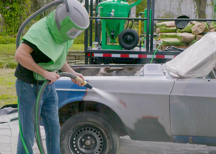
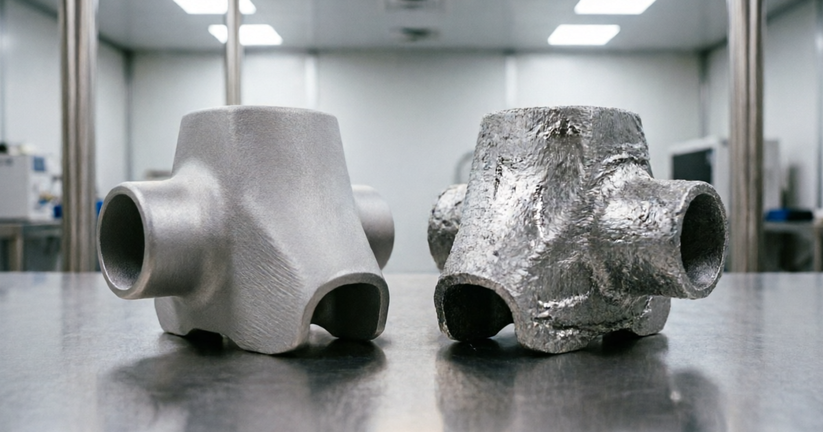
In additive manufacturing, the as-built surface is almost never the finished surface. Whether you are producing metal structural components via selective laser melting or functional prototypes with fused deposition modeling, the layer-by-layer build process leaves behind a surface texture that is routinely too rough, too contaminated, or insufficiently controlled for most end-use applications. Abrasive blasting — the controlled propulsion of abrasive particles against a surface under pneumatic pressure — has become one of the most widely adopted post-processing methods in professional AM workflows, offering a uniquely versatile combination of speed, material compatibility, and scalability that few competing technologies can match.
1. Why 3D Printed Parts Demand Surface Post-Processing
The surface of an as-built 3D printed part is the direct product of the build process’s fundamental mechanics — and those mechanics are inherently imperfect from a surface quality standpoint. Understanding why requires a brief look at what each major AM process actually does to the surface during the build.
In fused deposition modeling (FDM), each layer of extruded thermoplastic creates a visible ridge — the so-called stair-step effect. On vertical and near-vertical surfaces, this produces surface roughness (Ra) values typically between 10 µm and 30 µm, well above the specification of virtually every engineering application that matters. On flat top surfaces, Ra may be 5–12 µm, but layer lines are still visible to the naked eye.
In selective laser sintering (SLS), sintered powder particles form the surface, resulting in a granular, matte texture at Ra 10–20 µm. Multi Jet Fusion (MJF) produces slightly better surface quality — typically Ra 8–15 µm — but parts still exhibit visible powder texture and a characteristic mottled grey appearance from the fusing agent.
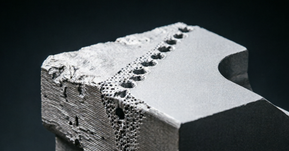
Metal AM processes — selective laser melting (SLM), direct metal laser sintering (DMLS), laser powder bed fusion (LPBF) — achieve Ra 8–20 µm on upward-facing surfaces, and substantially higher roughness on downward-facing (down-skin) surfaces and side walls, where partially melted powder particles adhere to the solidifying melt pool. Electron beam melting (EBM), which operates at higher temperatures with coarser powder feedstock, typically produces Ra 25–35 µm across most surfaces.
These surface conditions create measurable engineering problems across multiple performance dimensions:
- Fatigue and fracture: Surface asperities and layer-line notches act as stress concentrators. Studies on SLM Ti-6Al-4V consistently show that as-built fatigue strength can be 30–50% lower than machined or polished specimens due to surface-crack initiation. This is not a minor variance — it is a fundamental structural performance gap.
- Coating and adhesion failure: Coatings applied to surfaces contaminated with loosely adherent powder or non-uniform oxide films fail at the interface under thermal or mechanical cycling. Pre-blast surface preparation is mandatory for any durable coating application on AM parts.
- Corrosion susceptibility: Irregular surfaces trap moisture and contaminants. On stainless steel and titanium AM parts, the passive oxide layer may be non-uniform across the as-built surface, reducing corrosion resistance in service.
- Functional performance: Sealing surfaces, fluid channels, bearing races, and mating interfaces all require controlled surface textures that no current AM process can deliver without post-processing.
- Aesthetic requirements: Consumer products, medical devices, and precision instruments have visual surface quality requirements that are incompatible with visible layer lines or sintered powder texture.
The table below summarizes the practical surface roughness targets for common AM application categories, giving you an immediate sense of how large the gap is between as-built AM surfaces and the requirements of typical end-use applications:
| Application Category | Typical Ra Target (µm) | Can Blasting Achieve This Directly? |
|---|---|---|
| General structural engineering parts | 3.2–6.3 | Yes — typical blasting outcome |
| Pre-coating preparation (paint/primer) | 3–5 | Yes — primary use case |
| Medical implants (osseointegration surface) | 1.5–4.0 | Yes — glass bead blasting |
| Consumer aesthetics | 0.8–3.2 | Yes, for upper range; fine glass beads |
| Aerospace fatigue-critical parts | ≤ 1.6 | Partially — blasting + secondary finishing |
| Pre-PVD coating | 0.3–1.0 | No — blasting + electropolishing required |
| Hydraulic/pneumatic sealing surfaces | 0.4–1.6 | No — requires grinding or lapping after blasting |
Abrasive blasting addresses the upper tier of these requirements directly and serves as the essential preparation step before additional finishing processes for tighter specifications. In most AM production workflows, it is the first — and often the only — post-processing step applied to the part surface.
2. The Mechanics of Abrasive Blasting on AM Parts
Abrasive blasting propels a stream of particles — the blasting media — at the workpiece surface under controlled pressure, typically using compressed air (dry blasting) or a pressurized water-media slurry (wet or vapor blasting). When particles strike the surface at velocity, two fundamental mechanisms occur simultaneously, in proportions controlled by media type and process parameters:
Mechanism 1: Cutting and Abrasion (Etching Mode)
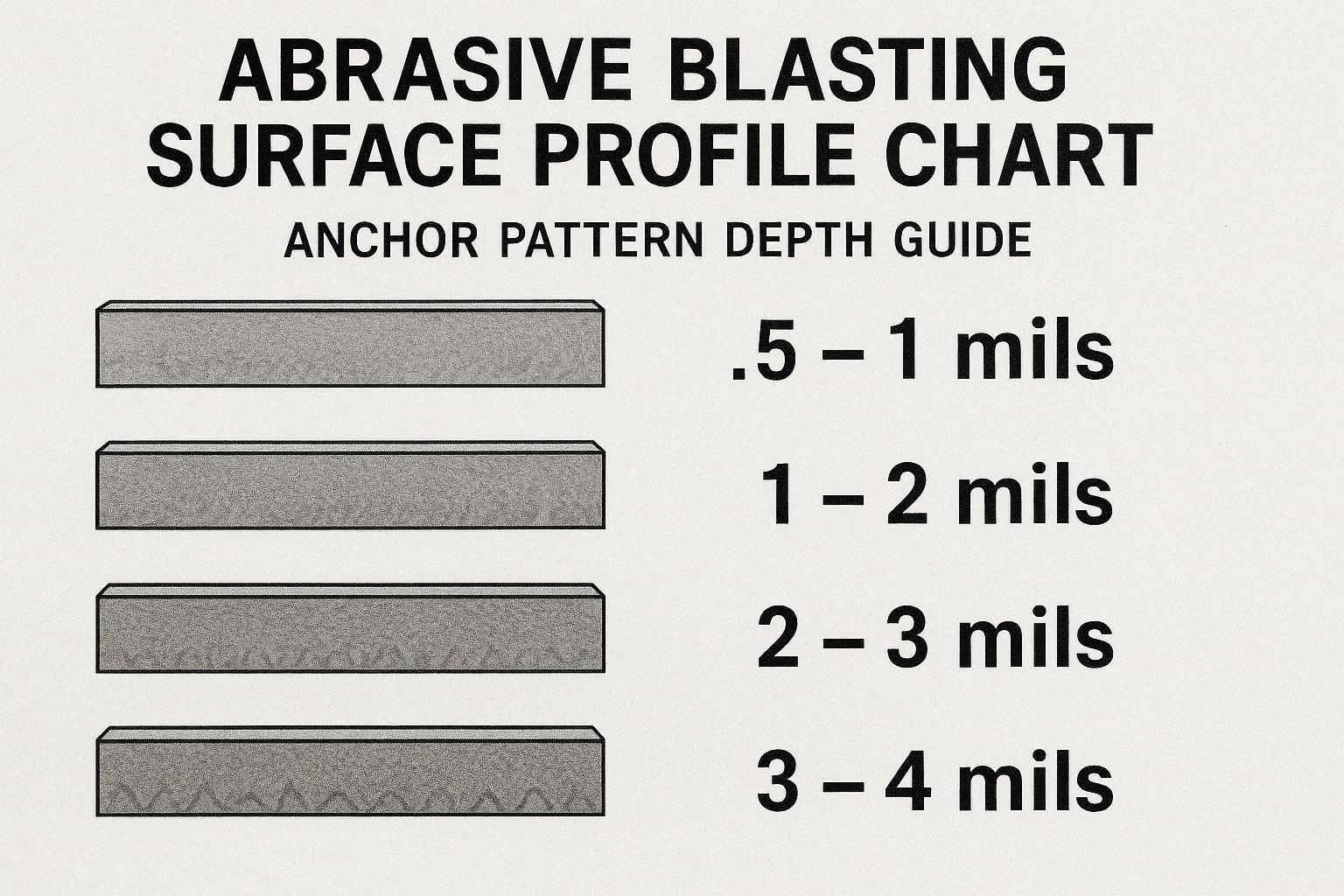
Angular particles with sharp edges remove material by micro-cutting action at the surface. Each impact creates a microscopic cutting event, removing the tops of surface peaks and leaving a uniformly etched texture. Angular aluminum oxide grit (Al₂O₃) operates primarily in this mode. The resulting surface carries a defined anchor profile — a controlled micro-roughness that provides excellent mechanical keying for adhesive coatings, paints, and thermal spray.
Mechanism 2: Plastic Deformation (Peening Mode)
Spherical particles — glass beads, steel shot, zirconia beads — deform the surface plastically without cutting it. Each spherical impact flattens the local surface asperity and drives a residual compressive stress zone into the surface layer. This is the operating mode of shot peening, and it is responsible for the fatigue life improvements achievable through blasting of metal AM parts. Unlike cutting, peening does not significantly increase surface Ra — it can actually reduce it slightly by flattening peaks.
关键过程变量
Six variables govern the outcome of any abrasive blasting process on a 3D printed part:
-
Media type and morphology — the single most consequential decision; determines whether you etch (angular) or peen (spherical), how fast material is removed, and what the final surface texture looks like. Media type must be matched to both the substrate material and the post-processing objective.
-
Media size (mesh or grit designation) — coarser media removes material faster and creates higher Ra values; finer media produces smoother surfaces but requires longer cycle times. For most metal AM applications, the useful range is 80–250 mesh.
-
Blast pressure (psi or bar) — determines particle velocity. Higher pressure delivers more energy per impact; too high and you risk part distortion, media embedding in soft alloys, or dimensional loss on thin features. Typical range: 25–90 psi depending on material.
-
Nozzle standoff distance — typically 6–14 inches from the part surface. Closer distances create more concentrated impact and higher local energy; farther distances create broader coverage patterns and softer impacts.
-
Nozzle angle to the surface — 90° delivers maximum peening energy; 45–75° is typical for general finishing; lower angles (20–45°) are used for undercuts and recessed features.
-
Coverage and dwell time — uniform 98–100% coverage is required for consistent results. Insufficient coverage leaves untreated patches that can be visible and create inconsistent surface properties.
The power of abrasive blasting for 3D printed parts lies in the adjustability of these six variables. A single blast cabinet can function as a surface cleaner, a Ra-reduction station, a pre-coating preparation line, and a fatigue-life enhancement system — simply by changing media and adjusting parameters for each application.
Angular media (Al₂O₃, steel grit) = etching mode → lower Ra through material removal, good coating anchor profile. Spherical media (glass beads, steel shot) = peening mode → surface smoothing + compressive stress induction. Most AM post-processing applications call for spherical media, with angular media reserved for aggressive cleaning and pre-coating prep.
3. Abrasive Blasting vs. Other AM Post-Processing Methods
3D printing post-processing is a competitive technology space. Multiple methods compete for the same surface quality goals, and the right choice often depends on material, geometry, production volume, and acceptable cost. Understanding where abrasive blasting excels — and where it does not — is essential before committing to a post-processing workflow.
| Method | Material Compatibility | Typical Ra Range (µm) | Internal Surfaces | Cost per Part | Key Limitation |
|---|---|---|---|---|---|
| Abrasive blasting | Metals + all polymers | 0.5–8 | Limited | Low–Med | Cannot reach deep internal passages |
| Chemical smoothing | Specific polymers only | 0.3–3 | Yes | Med | Hazardous solvents; alloy-limited |
| Vibratory tumbling | Metals + polymers | 0.4–4 | No | Low | Cannot process complex geometries |
| CNC machining/grinding | Metals mainly | 0.1–1.6 | Partial | High | Expensive; requires fixturing |
| Electropolishing | Conductive metals | 0.1–1.6 | Yes | Med–High | Alloy-specific; changes part geometry |
| Laser polishing | Metals | 0.1–0.5 | No | Very High | Slow; high capital cost |
| Manual sanding/filing | All | Variable | Partial | High (labor) | Inconsistent; not scalable |
Abrasive blasting wins decisively on the combination of material versatility, speed, production scalability和 unit cost — which is why it is the default first post-processing step in the vast majority of AM production lines. In many applications, it is the only step required. Where the specification demands Ra values below 0.8 µm (precision sealing, optical surfaces, PVD pre-treatment), blasting functions as the preparation stage before a secondary polishing process.
Chemical smoothing is the strongest competitor for polymer AM parts — particularly for FDM ABS (acetone smoothing) and for HP MJF nylon (commercial systems such as AMT PostPro). These processes can achieve Ra values as low as 0.2 µm and can reach internal passages. Their limitations — hazardous chemicals, limited material compatibility, slow batch cycles — make them less suitable for mixed-material production environments.
For metal AM parts, abrasive blasting is almost always the first and primary surface treatment, with electropolishing, vibratory superfinishing, or CNC machining added for features requiring tighter Ra specifications.
4. Blasting by AM Technology: FDM, SLS/MJF, and Metal AM
Each additive manufacturing technology produces a different as-built surface condition, and the optimal blasting approach varies substantially. This section covers the three major technology categories.
4.1 FDM and FFF 3D Printed Plastic Parts
Fused deposition modeling produces some of the roughest as-built surfaces of any common AM technology. The extruded bead structure creates highly directional texture, with Ra values of 10–25 µm on vertical surfaces and 5–12 µm on flat top surfaces. Layer lines are visible to the naked eye at typical layer heights of 0.1–0.3 mm, and these ridges function as stress concentrators that reduce the fatigue and impact resistance of the part.
Bead blasting with fine glass beads (150–250 mesh / 60–100 µm diameter) at 30–50 psi is the most effective and safest first post-processing step for FDM parts. The spherical glass beads operate in peening mode — they deform the layer-line ridges and surface peaks without aggressive material removal, creating a consistent, uniform matte surface. Typical Ra improvement: from 15–25 µm to 3–8 µm after a single blasting cycle. The blasted surface also accepts paint, primer, and UV-cure coatings significantly better than the as-built surface due to the improved surface uniformity and micro-texture.
Material-specific notes for FDM blasting: PLA and PETG perform well at low pressures (30–45 psi); ABS tolerates slightly higher pressures and also responds well to post-blast acetone wiping; Nylon (PA6/PA12 filament) is moderately durable under blasting; TPU and flexible filaments require very gentle treatment (20–35 psi, large standoff) to avoid deformation.
Key risk: thin walls below 1.2 mm wall thickness can crack or distort under sustained blast pressure, even at moderate settings. Complex infill-based prints with thin shells should be evaluated on a test coupon before committing production parts.
For a detailed FDM blasting protocol — including media selection tables for all major FDM materials, pressure recommendations by wall thickness, and before/after Ra measurement data — see: Bead Blasting FDM 3D Printed Parts: Smoothing Layer Lines and Finishing Plastic Surfaces.
4.2 SLS and MJF Nylon 3D Printed Parts
Selective laser sintering (SLS) and Multi Jet Fusion (MJF) both produce polymer parts from powder beds by selectively fusing polymer powder particles. The resulting surface is granular and matte — Ra typically 10–20 µm for SLS (PA12 nylon) and 8–15 µm for MJF — formed by partially fused and partially adherent powder particles. Loose powder also remains trapped in surface pores and recessed features after the build cycle, requiring active removal.
Abrasive blasting serves two distinct roles for SLS and MJF parts:
- Depowdering: Removing trapped surface powder from recesses, channels, and internal cavities. Plastic blasting media or low-pressure air blasting is standard for the depowdering stage, as the sintered part surface is still relatively fragile and requires gentle treatment.
- Surface conditioning: Improving surface uniformity and reducing Ra. Fine glass beads (150–200 mesh) at 35–50 psi produce a more consistent matte surface that is uniform across all build orientations — critical for parts that will be dyed, painted, or clear-coated.
MJF parts have a distinctive mottled grey appearance caused by the HP fusing and detailing agent chemistry. Blasting normalizes this appearance across the entire part surface, creating a uniform texture that accepts industrial dyes and coatings much more evenly. This makes blasting essentially mandatory in the MJF post-processing workflow for any part that will be colored or coated.
Achievable Ra for SLS/MJF after blasting: typically 2–5 µm from an as-built 10–20 µm, representing a significant quality improvement that enables parts to be used in functional assemblies without additional finishing.
For the full SLS vs. MJF surface conditioning workflow — including depowdering protocols, glass bead vs. plastic media selection for different nylon grades (PA11, PA12, PA12-GB), and color preparation procedures: Abrasive Blasting SLS and MJF Nylon 3D Printed Parts: Depowdering, Deburring, and Surface Prep.
4.3 Metal AM Parts: SLM, DMLS, and EBM
Metal additive manufactured parts present the most demanding and highest-consequence surface finishing challenges in the AM post-processing landscape. As-built Ra values from SLM/DMLS typically range from 8–20 µm on top surfaces and 20–35 µm on down-facing surfaces and side walls — caused by adherent partially melted powder particles and the stair-stepping effect of the layer scan strategy. EBM parts, which use coarser powder feedstock (typically 45–150 µm vs. 15–45 µm for SLM), commonly show even higher roughness: Ra 25–40 µm.
The as-built metal AM surface also carries a thin oxide layer formed during the laser or electron beam process. This oxide layer is non-uniform, often porous, and chemically distinct from the base metal — it must be removed before the part undergoes heat treatment, hot isostatic pressing (HIP), passivation, or coating.
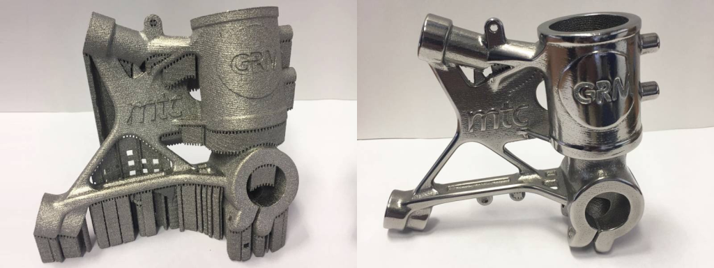
Shot blasting and bead blasting are the standard first post-processing steps in virtually all metal AM production lines. Typical achievable Ra after blasting: 1–5 µm, representing a 60–90% reduction in surface roughness. Media selection is critical and alloy-dependent: glass beads for stainless steel and titanium (to prevent iron contamination), aluminum oxide for aluminum alloys and tool steels, and steel shot or grit for carbon and alloy steels. This decision is covered in full in Section 5 of this guide.
For the complete metal AM blasting protocol — including blast sequence design, parameter tables for SLM titanium, Inconel, aluminum, and stainless steel, and guidance on integrating blasting with HIP and heat treatment sequencing: Shot Blasting Metal 3D Printed Parts: SLM, DMLS, and EBM Post-Processing Protocol.
5. Selecting the Right Blasting Media for 3D Printed Parts
The choice of blasting media is the single most consequential decision in designing a post-processing blast workflow for AM parts. The wrong media choice can contaminate the part surface, distort thin features, produce the wrong surface texture, or simply fail to achieve the required surface quality. The right media — matched precisely to the substrate material, part geometry, and post-processing objective — delivers consistent, repeatable, and documented results.
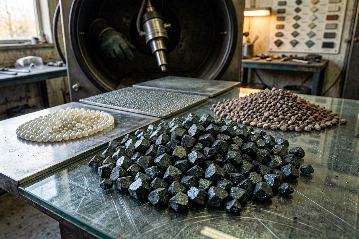
Four media families are used in the vast majority of AM post-processing applications:
玻璃珠
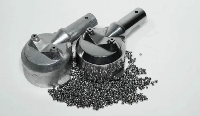
Glass beads are the dominant blasting medium for AM post-processing. Manufactured from borosilicate glass as true spheres to tight size tolerances, they operate in peening mode — deforming surface peaks without aggressive material removal. Their chemical inertness makes them safe for stainless steel, titanium, and medical applications where contamination by iron or other elements is unacceptable.
- Hardness: ~6 Mohs
- Shape: perfectly spherical
- Surface effect: uniform matte finish, no directional texture, slight compressive stress in surface layer
- Iron contamination risk: none
- Recyclability: excellent — can be reclaimed and reused until broken down below minimum mesh size
- Mesh size range used for AM: 80–400 mesh (coarser for aggressive treatment, finer for delicate parts)
- Best for: stainless steel, titanium, aluminum AM parts; SLS/MJF nylon; anodizing prep; medical and food-contact parts
Aluminum Oxide (Al₂O₃)
Aluminum oxide — also called alumina or corundum — is the standard choice for aggressive surface etching, anchor profile creation for coatings, and support mark removal. Its angular morphology creates sharp micro-cutting action at the surface, producing the highest anchor profiles of any common media type.
- Hardness: 9 Mohs (second only to diamond and silicon carbide)
- Shape: angular, irregular fracture planes
- Surface effect: etched texture with pronounced anchor profile; Ra is higher than glass beads at equivalent grit size
- Used grit sizes for AM: 80–120 (aggressive cleaning, support removal) and 150–220 (controlled pre-coating prep)
- Best for: pre-coating preparation on steel and Inconel AM parts; support fragment removal; aluminum alloy AM (carefully — embedding risk)
- Caution: can become embedded in soft alloys (AlSi10Mg, Al-Si10Mg). Use minimum necessary pressure and exposure time on aluminum parts.
Steel Shot and Steel Grit
Steel shot (spherical) is the classic shot peening medium. Steel grit (angular, crushed) is used for aggressive descaling and surface preparation on heavy industrial parts. Both are high-density media (approximately 7.8 g/cm³) that deliver maximum impact energy per particle.
- Hardness: 40–65 HRC depending on type (shot vs. grit, annealed vs. conditioned)
- Shape: shot = spherical; grit = angular
- Surface effect: shot → intense peening and compressive stress; grit → aggressive etching and cleaning
- AM shot sizes: S110 (0.28 mm) and S170 (0.43 mm) are most commonly used on AM parts, given their fine features
- Best for: shot peening carbon steel, alloy steel, and nickel superalloy AM parts for fatigue improvement; descaling carbon steel AM builds
- Not for: stainless steel parts (iron contamination), titanium parts (iron contamination), or polymer parts
塑料介质
Plastic blasting media (PMB) — typically polyester or acrylic — is the gentlest option for cases where neither glass beads nor aluminum oxide can be used without risking part damage. Its low hardness (2–4 Mohs) means it can clean and condition surfaces without removing significant material.
- Hardness: 2–4 Mohs
- Shape: varies (angular, rectangular, triangular cut shapes)
- Surface effect: gentle cleaning and de-powdering; minimal Ra improvement
- Best for: SLA/DLP resin prints, thin-walled FDM parts, SLS depowdering (first stage), stripping coatings from AM parts for rework
For a complete media selection guide — including a full compatibility matrix across all major AM alloys and polymers, expected Ra outcomes by media type and mesh size, and cost-per-cycle comparisons for production environments — see: Blasting Media for 3D Printed Parts: Glass Beads vs Aluminum Oxide vs Steel Shot — Selection Guide.
| 媒体类型 | Compatible AM Materials | Primary Objective | Typical Pressure | Typical Ra After Blasting |
|---|---|---|---|---|
| Glass beads 100–200 mesh | SS, Ti, Al alloys, nylon, polymers | Matte finish, cleaning, peening | 35–75 psi | 0.8–4 µm |
| Al₂O₃ 80–120 grit | Carbon steel, alloy steel, Inconel | Pre-coating anchor profile, aggressive cleaning | 50–80 psi | 2–6 µm |
| Al₂O₃ 150–220 grit | Most metals (carefully on Al) | Fine pre-coating prep | 45–65 psi | 1.5–4 µm |
| Steel shot S110–S230 | Carbon steel, alloy steel, Inconel | Shot peening, fatigue life improvement | 40–70 psi | 2–5 µm |
| 塑料介质 | Polymer AM parts, delicate plastics | Depowdering, gentle cleaning | 20–40 psi | Minimal change |
6. Blasting for Specific Post-Processing Goals
The same blasting technology serves four distinct post-processing objectives in AM workflows. Understanding which objective governs your application is essential for selecting the right parameters and measuring the right outcomes.
6.1 Support Structure Removal
Metal 3D printed parts require dense support structures to prevent overhanging features from collapsing or warping during the build. After the build cycle, supports are typically removed mechanically — by wire EDM cutting, band-sawing, or manual breaking — but this almost always leaves behind residual challenges: support stub marks on the surface, oxidized heat-affected zones at the cut interface, and occasionally small adherent support fragments that resist mechanical removal.
Abrasive blasting with angular aluminum oxide grit (36–80 mesh) at higher pressures (60–90 psi) is highly effective at resolving all three issues. The aggressive cutting action of angular Al₂O₃ grit attacks the hardened, oxidized surface at support attachment points and blends the irregularity into the surrounding surface texture. It simultaneously removes the heat-affected and oxidized layer that forms during wire EDM cutting — a layer that is chemically and mechanically distinct from the base metal and must be removed before the part can be anodized, passivated, or reliably coated.
For more complex internal support configurations — channels or enclosed cavities with support remnants where external blast nozzles cannot reach — pressurized abrasive slurry injection or internal blasting lances using flexible nozzle attachments may be required. These are specialized adaptations of standard blasting technology but use the same media and pressure principles.
For the full support removal workflow including media sequences by alloy, dimensional monitoring protocols, and case examples from production SLM titanium and Inconel parts: Removing Support Structures from Metal 3D Printed Parts with Abrasive Blasting.
6.2 Surface Roughness Reduction — Improving Ra and Rz
For most AM parts, surface roughness reduction is the primary objective of abrasive blasting. The goal is to reduce the as-built Ra — often 10–35 µm depending on process and build orientation — to a level compatible with the part’s functional and aesthetic requirements.
| AM Process | As-Built Ra (µm) | After Glass Bead Blasting (µm) | After Al₂O₃ Blasting (µm) |
|---|---|---|---|
| FDM Plastics (ABS, Nylon) | 10–25 | 3–8 | N/A |
| SLS Nylon (PA12) | 12–20 | 2–5 | N/A |
| MJF Nylon | 8–15 | 1.5–4 | N/A |
| SLM AlSi10Mg (aluminum) | 8–20 | 1–4 | 2–5 |
| SLM/DMLS Ti-6Al-4V | 8–18 | 1–3.5 | 2–5 |
| SLM 316L Stainless Steel | 8–18 | 1–4 | 2–6 |
| EBM Ti-6Al-4V | 25–40 | 2–6 | 3–8 |
| SLM Inconel 718 | 8–20 | 1–4 | 2–6 |
The key to achieving the lowest Ra values is selecting the finest appropriate media at the minimum workable pressure, with full and even coverage in multiple directions. A technique called cascade blasting — multiple passes with progressively finer media — can further reduce Ra. For example: a first pass with 80-mesh Al₂O₃ to remove oxide and major surface peaks, followed by a second pass with 200-mesh glass beads to create a uniform, fine matte surface.
When Ra values below 1 µm are required — for precision sealing surfaces, bearing interfaces, or PVD coating substrates — abrasive blasting alone is insufficient. Blasting should be specified as the pre-treatment step, followed by electropolishing, vibratory superfinishing, or lapping to reach the final specification.
For the complete Ra/Rz reduction protocol — including cascade blasting sequences, measurement methods per ISO 4287 and ISO 25178, and acceptance criteria by application type: Improving Ra and Rz on 3D Printed Parts: How Abrasive Blasting Reduces Surface Roughness.
6.3 Pre-Coating Surface Preparation
Whether you are applying liquid paint, powder coat, PVD, CVD, thermal spray, or an electroless coating, the coating system’s adhesion and service life depend fundamentally on the substrate surface condition at the moment of application. Coatings need three things from the substrate surface:
- Chemical cleanliness — free of oxides, oils, dust, loosely adherent particles
- A controlled surface profile (anchor pattern) for mechanical interlocking
- The correct Ra range for the specific coating chemistry
Abrasive blasting delivers all three in a single operation. For liquid paint and epoxy primers, an anchor profile equivalent to SSPC-SP6 (Commercial Blast) or ISO 8501-1 Sa 2 at Ra 3–5 µm is typically specified. Powder coating performs best at Ra 3–7 µm. Thermal spray coatings require a more aggressive profile (Ra 6–12 µm with Al₂O₃ 36–54 grit). PVD coatings, applied in a high-vacuum process, require a smooth, clean surface (Ra 0.3–1.0 µm) — which means blasting for cleaning followed by electropolishing or mechanical polishing to achieve final Ra.
Timing is critical for metals. The freshly blasted metal surface is chemically active and begins oxidizing immediately upon air exposure. For most metals, coating or conversion coating should follow blasting within 4 hours. For titanium and stainless steel, which passivate extremely rapidly, the window is 1–2 hours in clean, dry conditions.
For the full pre-coating workflow — including coating system compatibility tables, profile measurement standards, and blast specifications for each major coating type: Pre-Coating Surface Preparation for 3D Printed Parts: Blasting Before Paint, Powder Coat, and PVD.
6.4 Shot Peening for Fatigue Life Improvement
Shot peening is a precisely controlled form of abrasive blasting specifically engineered to introduce compressive residual stress into the surface and near-surface layer of a metal part. Unlike general bead blasting, shot peening is a fully quantified process governed by intensity specifications measured using Almen test strips (SAE J442, SAE AMS 2430, MIL-S-13165).
When a spherical shot particle strikes a metal surface, the local surface layer undergoes plastic deformation and attempts to expand laterally. The surrounding elastic bulk material constrains this expansion, placing the deformed surface layer in a state of biaxial compressive residual stress. This compressive stress counters the tensile stress at the surface that initiates and propagates fatigue cracks under cyclic loading.
Shot peening is particularly valuable for metal AM parts for a specific reason: SLM and DMLS parts typically contain tensile residual stresses in the as-built state, resulting from the rapid heating and cooling cycles of the laser process. Shot peening directly counters these as-built tensile stresses while simultaneously providing the general fatigue resistance benefits documented across decades of conventional manufacturing applications.
Documented fatigue life improvements from shot peening of metal AM parts (as of published literature through 2026):
- SLM Ti-6Al-4V: 25–65% improvement in high-cycle fatigue strength
- LPBF Inconel 718: 20–50% improvement
- SLM 316L stainless steel: 15–40% improvement
- SLM AlSi10Mg: 10–30% improvement
Shot peening intensity is specified and controlled by Almen strip arc height — typically Almen A (0.001–0.024″ arc height) for AM thin-walled structures, and Almen C for heavier sections. Coverage specification is 98–100% minimum for uniform compressive stress distribution.
For a full shot peening specification guide — including Almen intensity selection by alloy and section thickness, coverage verification methods, and aerospace/medical compliance documentation requirements: Shot Peening 3D Printed Metal Parts: Improving Fatigue Life with Compressive Residual Stress.
7. Material-Specific Blasting Protocols
The three alloy systems below account for the majority of industrial metal AM production volume in 2026. Each has distinct surface properties, contamination sensitivities, and downstream processing requirements that dictate specific blasting protocols.
7.1 AlSi10Mg — Aluminum Alloy 3D Printed Parts
AlSi10Mg (Al-Si10-Mg) is the most widely used aluminum alloy in SLM and LPBF, valued for its excellent laser processability, high strength-to-weight ratio (density 2.67 g/cm³), and good thermal properties. It is extensively used for lightweight aerospace brackets, automotive heat exchangers, and complex fluid manifolds. As-built parts show Ra 8–20 µm and exhibit a characteristic partially sintered powder texture across all non-top surfaces.
Blasting aluminum AM parts requires special care for two reasons. First, aluminum’s relatively low surface hardness (Mohs 2.5–3) means that hard angular media — especially Al₂O₃ — can become embedded in the surface under normal blasting pressures. Embedded media particles disrupt anodizing uniformity, create potential galvanic corrosion sites, and are unacceptable in food-contact applications. Second, excessive blast pressure can distort thin-walled aluminum sections (walls below 1.5 mm) that are common in topology-optimized AM parts.
Recommended protocols for AlSi10Mg:
- Finish blasting (pre-anodizing, matte finish): Glass beads, 100–200 mesh, 35–55 psi, 8–12-inch standoff, 60–75° angle, multi-axis coverage
- Aggressive cleaning (pre-coating with Al₂O₃): Fine aluminum oxide, 120–220 grit, 45–60 psi, 8–10-inch standoff, single pass — minimize total exposure time to reduce embedding risk
- Post-blast cleaning: Compressed clean dry air blow-off + ultrasonic washing in deionized water before anodizing
Anodizing performance on SLM AlSi10Mg is significantly improved by pre-blast surface preparation. The silicon-rich surface layer that forms on as-built AlSi10Mg during laser sintering creates an irregular anodic oxide layer with color inconsistency. Blasting removes this layer and creates a more uniform aluminum surface for the anodizing electrolyte to work on.
For the complete protocol — including pre- and post-blast cleaning procedures, anodizing compatibility data, and fixture design guidance for distortion-sensitive thin-walled parts: Blasting AlSi10Mg Aluminum 3D Printed Parts for Anodizing and Coating Adhesion.
7.2 Ti-6Al-4V — Titanium 3D Printed Parts
Ti-6Al-4V (Grade 5 titanium) is the workhorse of metal AM for aerospace, medical, motorsport, and defense applications — accounting for an estimated 35–45% of all metal AM production volume in 2026. It is processed by SLM, DMLS, EBM, and direct energy deposition (DED), across a very wide range of applications from turbine components to spinal implants.
As-built Ti-6Al-4V from SLM/DMLS shows Ra 8–18 µm. EBM titanium parts, built in a vacuum chamber, typically show higher roughness (Ra 25–35 µm) due to the coarser powder feedstock and higher processing temperature. Both surface conditions are incompatible with end-use performance requirements in aerospace (Ra ≤ 1.6 µm typical) and medical (Ra 1.5–4.0 µm for osseointegration) applications without post-processing.
Critical rule for titanium blasting: use only iron-free media — glass beads or zirconia beads (ZrO₂). Even trace quantities of embedded iron particles in a titanium surface compromise the passive titanium oxide layer (TiO₂), reducing corrosion resistance and — for medical implants — biocompatibility. Steel shot must never be used on titanium parts, regardless of application.
Recommended protocols for Ti-6Al-4V:
- Standard surface finishing (aerospace and industrial): Glass beads, 100–200 mesh, 55–75 psi, 8–12-inch standoff, 45–75°, clean dry compressed air supply
- EBM parts (higher starting Ra): Glass beads, 80–150 mesh, 60–80 psi, 8–10-inch standoff — coarser media needed to address higher starting roughness
- Medical implants (osseointegration target Ra 1.5–4 µm): Glass beads, 150–200 mesh, 55–65 psi — controlled to hit target Ra range
- Fatigue-critical aerospace parts: Glass beads or ZrO₂ beads for shot peening at Almen A 0.15–0.25″ intensity
- Post-blast (medical): DI water rinse + passivation rinse per ISO 13485 batch record requirements
For the complete protocol — including EBM-specific process differences, medical vs. aerospace specification differences, and fatigue performance data supporting shot peening specification for Ti-6Al-4V AM parts: Surface Finishing Ti-6Al-4V Titanium 3D Printed Parts: Blasting for Roughness Reduction and Fatigue Life.
7.3 316L Stainless Steel 3D Printed Parts
316L stainless steel is a widely used SLM/DMLS material for medical devices, fluid handling components, chemical processing equipment, food-contact parts, and general industrial applications. The “L” designation indicates low carbon content (≤ 0.03 wt%), which is important for maintaining corrosion resistance in parts exposed to elevated temperatures or weld heat-affected zones. In AM, this low carbon content also means that no post-build sensitization occurs, making 316L suitable for service in corrosive environments without post-build solution annealing in most cases.
As-built 316L from SLM shows Ra 8–18 µm across typical build surfaces, with a thin chromium- and iron-enriched oxide layer on the surface formed during the laser processing atmosphere. This as-built oxide layer is non-uniform and does not offer the same corrosion protection as the properly formed passive layer that develops after passivation on a clean surface.
Critical rule for 316L blasting: glass beads only — no steel shot or steel grit. Iron particles from steel media embedded in stainless steel create galvanic corrosion initiation sites and disrupt the passive chromium oxide layer. For medical and food-contact parts, even the slightest iron contamination is a compliance failure.
Recommended protocol for 316L:
- Surface finishing: Glass beads, 100–200 mesh, 50–70 psi, 8–12-inch standoff, 45–75°, multi-axis coverage
- Post-blast: Compressed clean dry air blow-off, then passivation within 2 hours of blasting (ASTM A967 or AMS 2700 citric acid or nitric acid passivation)
- For medical devices: Full batch documentation of media batch, blast equipment, operator, date, and passivation method required
Blasting immediately before passivation is strongly recommended because the freshly blasted 316L surface is free of the non-uniform oxide layer and presents the cleanest possible substrate for the passivating solution, resulting in a thicker, more uniform, and more corrosion-resistant passive film than passivation applied to the as-built surface.
For the complete 316L post-processing workflow — including blasting and passivation sequencing, cleanliness verification methods (ferroxyl test, ESCA surface analysis for medical), and regulatory documentation: Abrasive Blasting 316L Stainless Steel 3D Printed Parts: Finishing for Passivation and Quality Inspection.
8. Blasting Equipment for 3D Printed Parts
Equipment selection has a major impact on process efficiency, surface consistency, and suitability for different AM part geometries. 3D printed parts — with their complex geometry, thin walls, and often tight tolerances — benefit from more thoughtful equipment specification than is needed for simple fabricated parts.
Pressure vs. Suction (Siphon) Blast Cabinets
Direct pressure blast systems hold the media in a pressurized vessel and meter it through the blast gun with the full blast pressure acting on the media stream. This delivers 2–3× higher media velocity than a siphon system at equivalent air pressure — significantly faster cycle times and more effective treatment of hard metal AM parts. Direct pressure is the standard choice for metal AM post-processing.
Siphon (suction) blast systems draw media into the air stream using a venturi effect at the blast gun. The media velocity is lower, making the process gentler — appropriate for delicate polymer AM parts (SLA resin, thin-walled FDM) where direct pressure systems would risk damage.
Automated Blasting Systems for AM Production
At production scale, manual blast cabinet operation introduces inconsistency and limits throughput. Automated blast systems are the standard in professional AM post-processing facilities:
- Rotary table blast systems: The part rotates on a programmable turntable while fixed or programmable nozzles blast from multiple angles. Suitable for symmetric parts — turbine blades, implant components, flanges, and round brackets. Highly repeatable and easy to validate.
- Robotic blasting cells: A robot arm moves the blast nozzle around a stationary or fixturized part following a programmed path derived from the part’s CAD model. Best for complex geometry AM components with multiple features requiring different blast angles and pressures.
- Conveyor systems: Parts pass through a continuous blast zone on a conveyor. Highest throughput; suitable for large batches of similar AM parts with predominantly flat surfaces.
Wet / Vapor Blasting
Wet blasting (vapor blasting) mixes media and water into a slurry that cushions the impact energy. This produces a bright, very smooth surface finish without embedding risk — ideal for precision metal AM parts in medical and aerospace. The water also acts as a lubricant, extending media life. The trade-off is more complex equipment and part drying requirements.
Equipment Features to Specify for AM Applications
- Variable pressure control from 20–100 psi (to handle both delicate polymers and hard metals)
- Stainless steel cabinet interior (for processing stainless or titanium parts without risk of iron cross-contamination)
- HEPA-grade dust collector with adequate airflow to maintain negative cabinet pressure
- Media classification and reclaim system to remove fine dust and over-broken media, maintaining media quality over time
- Moisture separator and coalescing filter on the compressed air supply line (especially critical for medical and aerospace applications)
9. Process Parameters Reference Guide
The following table provides validated starting-point parameters for the most common 3D printed materials and objectives. All values should be treated as starting points and validated on representative test coupons before committing to production processing.
| Material / Process | Media | Mesh / Grit | Pressure (psi) | Standoff (in) | Angle (°) | Notes |
|---|---|---|---|---|---|---|
| FDM — PLA, PETG | 玻璃珠 | 150–200 | 30–45 | 10–14 | 45–75 | Test thin walls first; low pressure |
| FDM — ABS | 玻璃珠 | 120–200 | 35–50 | 10–14 | 45-90 | Tolerates slightly higher pressure |
| FDM — Nylon, TPU | 玻璃珠 | 150–250 | 25–40 | 10–14 | 45–75 | TPU: very low pressure only |
| SLS Nylon PA12 (depowdering) | 塑料介质 | — | 25–35 | 10–14 | 45–75 | Stage 1: loose powder removal |
| SLS Nylon PA12 (finishing) | 玻璃珠 | 150–200 | 35–50 | 8–12 | 60–90 | Stage 2: surface conditioning |
| MJF Nylon | 玻璃珠 | 150–200 | 35–50 | 8–12 | 60–90 | Pre-dye/color finishing standard |
| SLA / DLP Resin | 塑料介质 | — | 20–30 | 12–16 | 30–60 | Resin can be brittle; test first |
| SLM AlSi10Mg (finish) | 玻璃珠 | 100–200 | 35–55 | 8–12 | 45–75 | No steel media; post-clean for anodizing |
| SLM AlSi10Mg (pre-coat) | Al₂O₃ | 120–220 | 45–60 | 8–10 | 45–75 | Brief exposure; minimize embedding |
| SLM/DMLS Ti-6Al-4V | 玻璃珠 | 100–200 | 55–75 | 8–12 | 45–75 | Iron-free media only; clean air supply |
| EBM Ti-6Al-4V | 玻璃珠 | 80–150 | 60–80 | 8–10 | 60–90 | Coarser media needed for higher Ra |
| SLM 316L Stainless Steel | 玻璃珠 | 100–200 | 50–70 | 8–12 | 45–75 | No steel media; passivate within 2 h |
| SLM Inconel 718 / 625 | Glass beads or Al₂O₃ | 100–180 | 60–80 | 8–12 | 45-90 | High hardness tolerates higher pressures |
| Shot peening — Ti-6Al-4V | Glass beads or ZrO₂ | 100–150 | 55–75 | 6–10 | 70–90 | Almen A 0.15–0.25″ intensity; 100% coverage |
| Shot peening — Steel / Inconel | Steel shot | S110–S230 | 40–70 | 6–10 | 70–90 | Verify Almen intensity pre-blast |
| Support removal (metal AM) | Al₂O₃ | 36–80 | 65–90 | 6–10 | 60–90 | Targeted blast at support attachment areas |
Always run a minimum of three test coupons at the lowest recommended pressure before processing production parts. Increase pressure incrementally. For shot peening: perform Almen strip validation on a fixture that matches the part geometry before the production run. Document all settings for quality traceability.
10. Abrasive Blasting in Industry-Specific AM Applications
Different industries apply abrasive blasting to 3D printed parts for different reasons, under different regulatory frameworks, and to different quality standards. This section covers the major application areas in detail.
Aerospace and Defense
Aerospace is the leading industry for metal AM adoption in 2026 by production value. Engine components, structural brackets, fuel nozzles, heat exchangers, and satellite hardware are all being produced via AM at commercial scale. The regulatory environment is correspondingly demanding: parts must comply with AS9100 (quality management), NADCAP (special processes including surface treatment), and customer-specific material and process specifications.
Abrasive blasting is a required documented step in the manufacturing plan (MFP) for the vast majority of aerospace metal AM parts. It is specified for surface cleaning, Ra compliance, pre-coating preparation, and — for fatigue-critical structural components — shot peening with full Almen intensity documentation and traveler traceability. In NADCAP-audited blast operations, the media type, batch number, blast pressure, operator qualification, equipment calibration date, and inspection results are all recorded in the part’s manufacturing record.
For complete coverage of aerospace AM blasting standards, NADCAP audit requirements, approved media specifications, and surface finish callout interpretation per ASME B46.1 and MIL-STD-1246: Abrasive Blasting for Aerospace Additive Manufacturing Parts: Surface Standards, Media Selection, and Compliance.
Automotive and Motorsport
Formula 1 teams, endurance racing organizations, and high-performance automotive OEMs have been aggressive early adopters of AM for topology-optimized brackets, titanium suspension components, aluminum heat exchangers, and aerodynamic inserts. Development cycles measured in weeks and the need for immediate production-quality surfaces make fast, reliable post-processing essential.
Automotive AM blasting focuses on three main applications: pre-painting surface preparation for aesthetic body and interior components; pre-thermal-coating surface preparation for heat management parts (ceramic coatings on exhaust and manifold components); and fatigue life improvement via shot peening on loaded structural brackets and suspension parts. Glass beads and aluminum oxide are the most commonly used media across these applications.
Medical Devices and Implants
Medical-grade metal AM is expanding rapidly. Titanium spinal cages, dental implant abutments, acetabular cups, and custom orthopaedic implants are produced in ISO 13485-certified AM facilities under full regulatory supervision. For these parts, blasting is not simply a surface conditioning step — it is a clinically significant process that directly affects implant performance.
For bone-contacting surfaces on titanium implants, the controlled surface roughness created by glass bead blasting (Ra 1.5–4.0 µm) has been clinically validated to promote osseointegration — the biological attachment of bone cells to the implant surface. Surface textures in this Ra range outperform both smoother and rougher surfaces in long-term clinical osseointegration studies. This means that blasting parameters for medical implants are specified as clinical performance requirements, not just manufacturing housekeeping — and they must be validated, controlled, and documented accordingly.
Dental applications include zirconia crown and bridge frameworks (blasted with Al₂O₃ before sintering to improve bonding surface), cobalt-chrome frameworks (blasted for porcelain adhesion), and PEEK-based prosthetics (plasma treatment or fine glass bead blasting for adhesive bonding).
Consumer Products and Footwear
Consumer AM applications — customized footwear midsoles from TPU lattice structures, bespoke electronics housings, decorative objects — require uniform surface finishes consistent across large production batches. Glass bead blasting is the standard post-processing step for consumer AM products because it delivers the consistent matte surface texture that characterizes premium AM consumer goods, at the production throughput rates that consumer markets demand.
Industrial Tooling and Fixtures
AM-produced tooling — H13 tool steel conformal cooling inserts, maraging steel dies, and jigs and fixtures — is routinely blasted for surface cleaning and pre-nitriding or pre-PVD coating preparation. Shot blasting with steel grit is standard for heavy tool steel AM components, followed by gas nitriding or PVD TiAlN coating to extend tool life. Blasting before nitriding improves nitrogen diffusion uniformity by creating a clean, oxide-free surface.
Explore the detailed post-processing guides for each AM application and material category in our complete resource library:
11. Quality Control After Abrasive Blasting
Blasting a 3D printed part is not complete until the surface quality has been verified against the applicable specification. For production AM workflows — especially in aerospace, medical, and automotive — quality control after blasting is a required documented step, not an optional check.
Surface Roughness Measurement
Contact profilometers (stylus instruments) measure Ra and Rz profiles per ISO 4287 / ASME B46.1. For AM parts — where surface texture is three-dimensional and anisotropic (Ra varies with direction due to build orientation and scan pattern) — areal surface texture measurement per ISO 25178 provides a more complete characterization than a single-line profile. Sa (areal average roughness) and Sz (maximum height over the evaluation area) are the areal equivalents of Ra and Rz.
Practical acceptance criterion: Ra within ±20% of the nominal target across all specified surface zones, measured in at least two perpendicular directions. Document measurement location, instrument calibration date, and operator on the part record.
Cleanliness and Contamination Inspection
After blasting, inspect for:
- Embedded media particles: Risk is highest when blasting soft alloys (AlSi10Mg) with hard angular media (Al₂O₃). Inspect visually under ×10 magnification; confirm with SEM energy-dispersive spectroscopy (EDS) for medical or aerospace parts.
- Iron contamination on stainless and titanium: Detect with ferroxyl indicator swab test (potassium ferricyanide solution). Blue coloration indicates iron contamination and requires re-cleaning and re-inspection. This test is mandated in many medical device manufacturing plans.
- Residual blast media on the surface: Blow off with clean dry compressed air; inspect visually and under UV lamp (fluorescent dye-impregnated media, if used, will be revealed).
Dimensional Verification
For tight-tolerance features, take CMM or calibrated dimensional measurements before and after blasting. Material removal per pass ranges from 0.005–0.05 mm depending on media and pressure. For most engineering tolerances (±0.1 mm or wider), this is negligible. For precision fits and critical surfaces with ±0.025 mm or tighter tolerances, the blast-induced material removal must be factored into the process control plan.
Documentation and Traceability
For regulated industries (aerospace, medical), the blast record should capture: part serial number or batch lot, blast date, equipment ID and calibration status, media type, batch/lot number, and certification, blast pressure and standoff distance, operator qualification number, inspection results, and any non-conformances with disposition. This documentation forms part of the part’s device history record (DHR) in medical manufacturing and the traveler in aerospace manufacturing.
12. Safety and Environmental Compliance
Professional abrasive blasting operations in AM post-processing facilities operate under occupational health regulations that have become significantly more stringent in recent years, particularly around airborne particulate exposure.
Silica-Free Media Requirement
OSHA’s respirable crystalline silica standard (29 CFR 1910.1053, effective 2018 in the US) restricts worker exposure to respirable crystalline silica to a PEL of 50 µg/m³ as an 8-hour time-weighted average. Traditional sandblasting using silica (quartz) sand produces airborne respirable silica dust far in excess of this limit and has been eliminated from professional AM post-processing operations. All media described in this guide — glass beads (amorphous silica, not crystalline), aluminum oxide, steel shot, and plastic media — comply with OSHA requirements when used in properly engineered enclosed blast systems.
Personal Protective Equipment
For manual blast cabinet operation and for maintenance activities where media or dust exposure is possible:
- Blasting hood with supplied-air respirator (NIOSH TC-19C approved, per 29 CFR 1910.134)
- Heavy-duty gloves — leather for metal parts with sharp edges; rubber or neoprene for chemical-resistant applications
- Hearing protection if in-cab blast noise exceeds 85 dB(A) — mandatory at 90 dB(A)
- Safety glasses and face shield when loading/unloading parts outside the blast cabinet
Dust Collection and Ventilation
All blast cabinets must be connected to a HEPA-grade dust collector maintaining sufficient airflow to hold the blast chamber at negative pressure relative to the surrounding work area. Filter condition must be checked and maintained on a scheduled basis — a clogged filter reduces cabinet airflow, allows dust to escape into the work area, and degrades blast performance by reducing cabinet visibility. Exhaust from the dust collector must be filtered to local environmental emission standards before atmospheric release.
Media Disposal and Environmental Compliance
Most abrasive blast media is recyclable. Glass beads are reclaimed, classified to remove fines, and reused until they fall below minimum mesh size specification. Steel shot and steel grit are also recyclable in steel mills. When blasting parts made from heavy-metal alloys — nickel, cobalt-chrome, chromium, beryllium copper — the used media, blast dust, and blast cabinet sweepings may be classified as hazardous waste under RCRA (US) or local equivalent regulations, requiring characterization, manifesting, and disposal through a licensed hazardous waste contractor. Always test blast waste from new alloy systems before assuming standard disposal applies.
13. Frequently Asked Questions
Can you abrasive blast any type of 3D printed material?
Most 3D printed materials — plastics and metals alike — can be abrasive blasted, but process parameters must be carefully matched to the material’s mechanical properties and geometry. Hard metals such as titanium, stainless steel, Inconel, and tool steel handle a wide range of pressures and media types with little risk. Soft aluminum alloys require lower pressures and spherical media to prevent embedding. FDM thermoplastics (PLA, ABS, Nylon, PETG) work well at 30–50 psi with glass beads; TPU and flexible filaments require very low pressures. SLA/DLP resin prints can be brittle and require particularly gentle treatment — plastic media at 20–30 psi — with prior testing on a representative coupon.
The absolute requirement is matching the media type and pressure to the specific material. The most critical restrictions: no iron-based media on titanium or stainless steel; no high pressure on thin-walled or lattice structures; no Al₂O₃ on aluminum when embedding risk is unacceptable.
What surface roughness (Ra) can I expect after abrasive blasting a metal 3D printed part?
Typical achievable Ra after glass bead blasting of metal AM parts: 1–4 µm, starting from an as-built Ra of 8–25 µm (SLM/DMLS) or 25–40 µm (EBM). Aluminum oxide blasting typically yields Ra 2–6 µm but provides a better anchor profile for subsequent coating. The exact outcome depends on the media mesh size, pressure, starting Ra, and number of passes.
For reference: CNC machining achieves Ra 0.4–3.2 µm, laser polishing 0.1–0.5 µm, and electropolishing 0.1–1.6 µm. When Ra values below 0.8 µm are required, abrasive blasting should be followed by one of these secondary processes.
How does abrasive blasting affect the dimensional accuracy of 3D printed parts?
Light glass bead blasting at low to moderate pressure removes approximately 0.005–0.05 mm of material per pass. For most engineering parts with tolerances of ±0.1 mm or wider, this material removal is negligible and can be ignored in process planning. For tight-tolerance features — press fits, precision bores, sealing surfaces at ±0.025 mm or tighter — dimensional measurements should be taken before and after a test blast cycle to quantify the specific material removal rate for your process.
The second dimensional risk is media embedding in soft alloys (particularly AlSi10Mg aluminum). Embedded particles slightly raise the local surface and can change the effective part dimension on critical bearing surfaces. Use the minimum necessary media hardness and exposure time for aluminum applications.
Which blasting media should I use for titanium 3D printed parts?
For all titanium AM parts — Ti-6Al-4V, Ti-6Al-2Sn-4Zr-2Mo, commercially pure titanium — glass beads are the required baseline media. They are chemically inert and free of iron contamination, which is critical because embedded iron particles disrupt titanium’s passive TiO₂ surface layer, reducing corrosion resistance and — in medical applications — biocompatibility. Steel shot and steel grit must never be used on titanium parts.
For fatigue-critical aerospace titanium parts where shot peening is specified, zirconia shot (ZrO₂) provides higher density and peening energy than glass beads without iron contamination risk. Zirconia shot is the preferred choice in NADCAP-compliant shot peening of titanium aerospace components where glass beads cannot deliver the required Almen intensity.
Is abrasive blasting better than chemical smoothing for 3D printed parts?
The answer depends on the material and surface quality requirement. Chemical smoothing (acetone for ABS, commercial solvent systems for PA12 and other polymers) can achieve Ra values as low as 0.2 µm and can treat internal passages — surfaces that abrasive blasting cannot reach. For polymer parts with internal channels requiring smooth, consistent surfaces, chemical methods may be superior.
Abrasive blasting has several important advantages: it works on virtually all materials (plastics and metals), introduces no chemical contamination, is faster for production volume, does not require hazardous solvent handling infrastructure, and is the only option for metal AM parts. For metal AM parts, chemical smoothing is not a viable alternative — abrasive blasting, electropolishing, or mechanical finishing are the available options. For polymer AM parts where only external surfaces need treatment and Ra 2–6 µm is sufficient, blasting is typically faster, cheaper, and easier to scale.
How long does it take to abrasive blast a 3D printed part?
Cycle time varies widely by part size, geometry, and the surface coverage required. A bracket-sized metal AM part (approximately 100 × 100 × 50 mm) typically requires 3–10 minutes of blasting for complete coverage in a manual blast cabinet. More complex geometries with undercuts, internal recesses, or lattice structures require repositioning and longer cycles.
Automated blasting systems — rotary table cells, robotic blast systems — reduce per-part time significantly by eliminating manual repositioning and running multiple parts simultaneously. In production AM post-processing facilities, per-part blast cycle times of 1–4 minutes are typical for bracket-scale components. High-volume SLS/MJF nylon post-processing runs can achieve much higher throughput through batch processing in automated tumble-blast systems.
Can abrasive blasting improve the fatigue life of 3D printed metal parts?
Yes — through the specific process of shot peening, which uses spherical media to introduce compressive residual stress into the surface layer. This compressive stress directly opposes the tensile stress that drives fatigue crack initiation and propagation. For metal AM parts, this is particularly significant because the SLM/DMLS build process itself introduces tensile residual stress in the as-built surface — which shot peening directly counters.
Published data (as of 2026) shows fatigue life improvements of 25–65% for SLM Ti-6Al-4V, 20–50% for LPBF Inconel 718, and 15–40% for SLM 316L stainless steel after shot peening, compared to as-built specimens. Shot peening is specified by Almen intensity (SAE AMS 2430) and requires controlled, documented process parameters for aerospace and medical applications.
What is the difference between bead blasting and shot blasting for 3D printed parts?
Both terms describe the same fundamental process — propelling particles at a surface under pressure — but they differ in the media type and the intended outcome. Bead blasting uses spherical glass or ceramic beads at low-to-moderate pressures (25–70 psi) for surface cleaning, matte finishing, and light peening of polymer and precision metal parts. The spherical beads do not aggressively cut the surface; they produce a uniform, matte, non-directional texture.
Shot blasting uses denser, larger, harder spherical steel balls (shot) or angular steel grit at higher energies, primarily for descaling, aggressive surface treatment, and shot peening of heavy metal parts. Shot blasting equipment typically operates at higher throughputs than blast cabinets and is designed for large batch processing of production metal components. For 3D printed parts, bead blasting covers the majority of finishing and cleaning applications; shot blasting is applied to metal AM components where fatigue life improvement through shot peening is the primary goal.
Source High-Performance Blasting Media for Your AM Post-Processing Line
Jiangsu Henglihong Technology Co., Ltd. manufactures glass beads, aluminum oxide, steel shot, and specialty blasting media for professional AM post-processing operations worldwide. Our technical team can assist with media selection, process parameter guidance, and sample evaluation for your specific AM materials and applications.
Contact Our Technical TeamPublished July 2026 by Jiangsu Henglihong Technology Co., Ltd. — Specialists in industrial abrasive blasting media for additive manufacturing post-processing.
过滤器