SLA Surface Treatment for Implants: The Sandblasted Large-Grit Acid-Etched Process — Parameters, Science, and Clinical Evidence
The SLA process is the most consequential surface treatment innovation in implant history. In the three decades since its clinical introduction, it has been applied to hundreds of millions of dental and orthopedic implants, validated in thousands of controlled clinical trials, and set the benchmark against which every new implant surface must be measured. Yet despite this ubiquity, the physics and chemistry of SLA — why the two-step sequence of blasting followed by acid etching produces a surface so consistently superior to either treatment alone — is rarely explained at the mechanistic level. This guide fills that gap. It covers the kinetics of particle impact and crater formation, the grain boundary chemistry of acid etching, the dual-scale roughness quantification methods that characterize the result, and the clinical evidence base that has established SLA as the gold standard it is.
1. Origin and Rationale of the SLA Concept
By the mid-1980s, two independent lines of research had established that titanium surface roughness significantly influenced early bone formation at the implant interface. Animal studies comparing machined (turned) titanium implants with roughened versions showed consistently higher bone-to-implant contact (BIC) ratios for roughened surfaces at early time points (2–4 weeks). The mechanism was not yet fully understood, but the practical implication was clear: the smooth, turned surface that machining produces is not optimal for osseointegration.
The question was how to create that roughness in a controlled, reproducible way that could be validated for clinical use. Two candidate processes existed: blasting (which created macro-roughness efficiently but left a work-hardened surface layer of uncertain biocompatibility) and acid etching (which created micro-roughness but no macro-scale features). The SLA insight was that these processes were synergistic rather than competitive — blasting first to create macro features, then etching to create micro features and simultaneously remove the blasting-induced surface artifacts, produced a surface with dual-scale roughness at both scales that cells could respond to simultaneously. The clinical validation of this hypothesis through controlled trials in the 1990s established SLA as the dominant implant surface treatment globally.
2. Phase 1 — Blasting: Particle Kinetics, Impact Mechanics, and Crater Formation
Understanding the physics of the blasting phase requires considering what happens during the approximately 10–100 microseconds of a single particle impact event.
Particle Velocity and Kinetic Energy
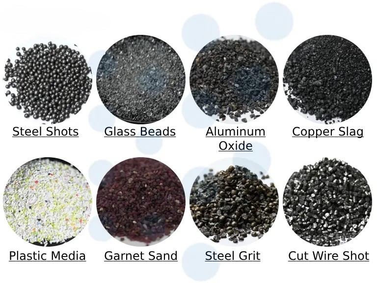
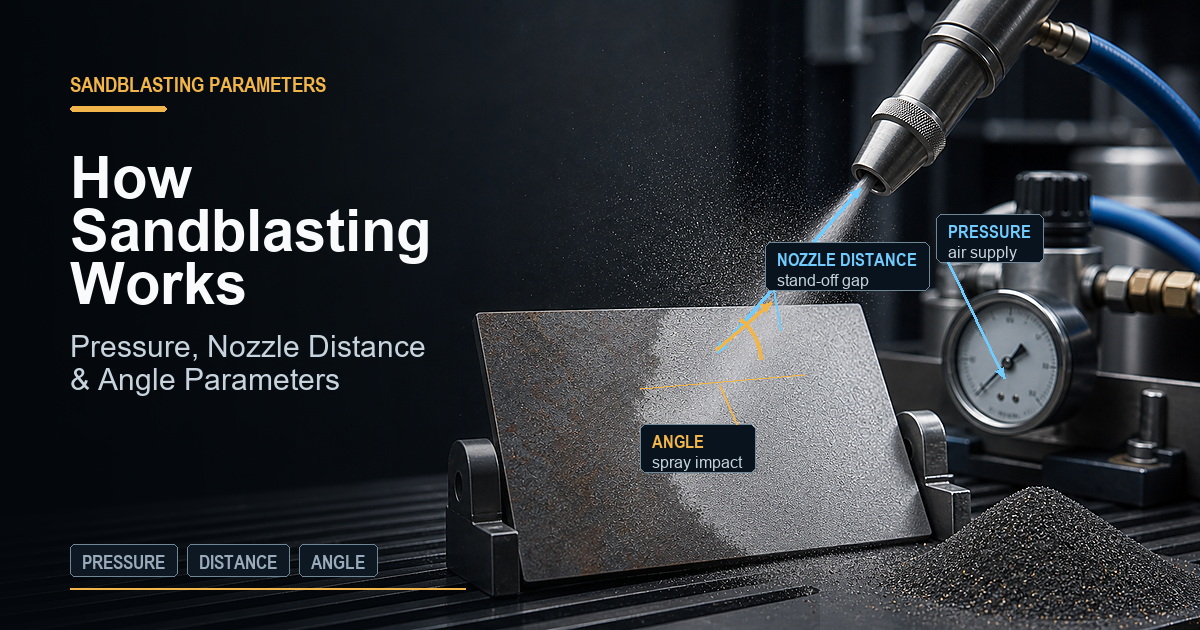
In a pressure-blast system at 3 bar, 250–500 μm Al₂O₃ particles are accelerated through the nozzle to velocities of approximately 50–150 m/s, depending on particle mass, nozzle geometry, and air pressure. The kinetic energy of a single particle is proportional to ½mv² — a 300 μm Al₂O₃ particle (density ~3.95 g/cm³) at 100 m/s carries approximately 0.56 μJ of kinetic energy. While this seems tiny, it is concentrated over the ~50 μm² contact area of the particle tip, creating a local contact pressure of approximately 10–30 GPa during impact — far exceeding the yield strength of both the particle and the titanium substrate.
Impact Mechanics and Crater Geometry
Upon impact, both the Al₂O₃ particle and the titanium surface deform. The titanium surface deforms plastically to create an impact crater whose geometry is determined by the particle shape, velocity, and impact angle. Angular Al₂O₃ particles create asymmetric craters with sharp ridges between impacts — the characteristic “peaky” morphology of blasted titanium surfaces seen by SEM. These crater geometries have specific dimensions: crater diameter approximately 0.5–2× the particle diameter (125–1000 μm for 250–500 μm particles), crater depth approximately 5–20% of particle diameter (12–100 μm). The macro-roughness created by these overlapping craters — Ra 2–4 μm for standard SLA blasting parameters — represents the macroscale of the dual-scale surface.
Work-Hardening and Residual Stress
Beneath each crater, a work-hardened zone extends 5–30 μm into the substrate with elevated dislocation density, increased hardness, and biaxial compressive residual stress. The work-hardened zone has a different etch response than undeformed titanium — it etches faster and with different morphology. The SLA acid etch step removes this layer completely, which is why etch time and temperature are critical process parameters: under-etching leaves work-hardened material that would produce different micro-pit morphology than specified; over-etching removes the macro-roughness peaks.
3. Phase 2 — Acid Etching: Grain Boundary Attack and Micro-Pit Formation
The acid etching phase acts on the work-hardened, macro-rough blasted surface to create a second (micro) scale of roughness while simultaneously removing the blasting artifacts. The chemistry of HCl/H₂SO₄ etching of titanium operates through two parallel mechanisms:
Grain Boundary Etching
Titanium’s hexagonal close-packed (HCP) crystal structure at room temperature (alpha phase) contains grain boundaries — the interfaces between differently oriented crystal grains that are several micrometers across. Grain boundaries have higher chemical reactivity than grain interiors because the crystal structure is disrupted at the boundary, increasing the local free energy. HCl attacks grain boundaries preferentially, dissolving titanium faster along these interfaces than across grain faces. The result is a network of micro-grooves following the grain boundary geometry, creating pits 0.5–3 μm deep and 1–5 μm across — the micro-scale of the SLA dual-scale surface.
Work-Hardened Layer Removal
The work-hardened surface layer introduced by blasting has elevated dislocation density, which also increases chemical reactivity relative to the undisturbed bulk material. The acid preferentially dissolves this layer, acting to remove the blasting artifacts — the compressed, smeared surface that would otherwise present a different biological surface to cells than the intended grain-boundary micro-pitted texture beneath. Complete removal of the work-hardened layer is confirmed in SEM cross-sections by the absence of a distinct deformation zone at the surface, and by the change in Ra from approximately 3 μm (post-blast) to 1–2 μm (post-etch) as the sharp blast-created peaks are rounded and partially dissolved.
Alumina Particle Dissolution
HCl/H₂SO₄ also dissolves surface-adhered Al₂O₃ blasting media particles, reducing (though not eliminating) the alumina contamination introduced by blasting. The dissolution rate of Al₂O₃ in HCl is lower than that of titanium under these conditions, which is why extended etching can reduce but not eliminate embedded alumina in the first 1–5 μm of the surface. This limitation is the primary driver of the shift to TiO₂ and ZrO₂ blasting media.
4. Dual-Scale Roughness: Quantification by Profilometry, AFM, and SEM
The defining characteristic of the SLA surface — and the property most directly linked to its clinical superiority over single-treatment surfaces — is the dual-scale roughness hierarchy. Quantifying both scales requires multiple complementary characterization methods.
Macro-Scale (From Blasting)
- Ra 2–4 μm (before etch)
- Feature size: 5–20 μm diameter craters
- Characterized by: contact profilometry (ISO 4287), cutoff λc 0.8 mm
- SEM magnification: ×100–×500
- Biological relevance: fibrin clot anchoring, osteoprogenitor cell migration scaffold
Micro-Scale (From Acid Etching)
- Ra 0.5–1.5 μm (post-etch measurement with λc 0.08 mm)
- Feature size: 0.5–5 μm diameter pits
- Characterized by: optical profilometry (ISO 25178), AFM
- SEM magnification: ×2000–×10000
- Biological relevance: individual integrin receptor engagement, osteogenic differentiation signaling
The three-dimensional characterization parameters from ISO 25178 areal surface texture are increasingly important for SLA surface specification. Sdr (developed interfacial area ratio) quantifies the actual surface area increase relative to a flat plane — SLA surfaces typically show Sdr values of 30–80%, meaning the cell-available surface area is 30–80% greater than the projected footprint area. Ssk (skewness) characterizes whether the surface has predominantly peaks or valleys: SLA surfaces typically show negative Ssk (valley-dominated texture created by acid-etched pits), which is associated with better osteoblast spreading than peak-dominated (positive Ssk) surfaces.
5. How Dual-Scale Roughness Drives Osseointegration
The clinical superiority of SLA over single-treatment surfaces emerges from the way the two roughness scales engage different biological processes at different organizational levels during bone healing:
Macro-scale (2–4 μm Ra) effects: At the scale of tissue organization, the macro-rough blasted surface creates a three-dimensional mechanical scaffold for fibrin clot organization in the peri-implant gap. The clot — which bridges the gap between implant surface and bleeding bone — must anchor to the implant surface to resist displacement under early loading. The 5–20 μm crater geometry of the blasted surface provides interlocking sites for fibrin fibers, maintaining clot stability during the critical first 72 hours when mesenchymal stem cells migrate through the clot toward the implant surface. A smooth surface provides no clot anchoring; a macro-rough SLA surface provides abundant anchoring geometry at the fibrin fiber scale.
Micro-scale (0.5–1.5 μm Ra) effects: At the cellular level, osteoprogenitor cells arriving at the implant surface probe the surface topography with focal adhesion complexes — clusters of integrin receptors spanning approximately 50–200 nm individually, grouped in assemblies of 0.5–5 μm scale. The micro-pits created by acid etching are precisely in the size range of focal adhesion complexes, providing the geometric features that maximally engage integrin-mediated mechanosensing. This mechanosensing triggers intracellular signaling (primarily through the FAK-MAPK pathway) that upregulates osteogenic transcription factors and commits the cell to osteoblast differentiation rather than fibroblast differentiation.
6. SLA Variants: SLActive, Hydrophilic Modifications, and Proprietary Systems
| Surface | Manufacturer | SLA Modification | Clinical Advantage |
|---|---|---|---|
| SLActive | Straumann | Post-etch handling under N₂; stored in isotonic NaCl. Hydrophilic surface. | Higher ISQ at 2–4 weeks; enables 4-week loading protocol in good bone |
| Ossean | Intralock | SLA + vacuum-driven Ca/P ion impregnation | Enhanced bioactivity; better performance in compromised/low-density bone |
| OsseoSpeed | Dentsply Sirona | TiO₂ blasting (no Al) + dilute HF etch; fluoride-modified surface | Fluoride incorporation promotes osteoblast differentiation; good in low-density bone |
| Laser-Lok | BioHorizons | Laser microtexturing (not SLA) on collar zone; SLA-equivalent on body | Crestal bone maintenance claim through epithelial/connective tissue attachment at collar |
| Roxolid SLActive | Straumann | SLActive process on Ti-Zr alloy | Smaller-diameter implants with equivalent osseointegration to standard-diameter Ti |
7. SLA vs TPS, HA Coating, and Laser Surface Treatment
| Traitement de surface | Ra / Scale | Osseointegration Speed | Long-term Stability | Manufacturing Complexity | Contamination Risk |
|---|---|---|---|---|---|
| SLA | 1–2 μm (dual-scale) | 4–6 weeks | Excellent (decades of data) | Medium (2 controlled steps) | Al contamination if Al₂O₃ media; manageable |
| Titanium Plasma Spray (TPS) | 40–80 μm Ra; porous | 6–12 weeks | Good (risk of coating delamination long-term) | High (plasma spray equipment, QC) | Faible |
| HA Plasma Spray | 50–100 μm Ra; porous HA | 4–6 weeks (faster in poor bone) | HA dissolves over 5–10 years; bone fills void | High (ASTM F1609 compliance) | HA resorption creates void; variable |
| Acid-etch only (no blast) | 0.5–1.5 μm (micro only) | 6–10 weeks | Good where bone contact uniform | Low (single step) | Faible |
| Laser ablation | Programmable; 1–50 μm | 4–8 weeks (limited data) | Promising but less clinical data | Medium-High (laser equipment, programming) | None (no media contact) |
8. Dental vs Orthopedic SLA: Parameter Differences
| Paramètres | Dental SLA | Orthopedic SLA | Reason for Difference |
|---|---|---|---|
| Substrate material | CP-Ti or Ti-6Al-4V | Ti-6Al-4V ELI primarily | Different hardness response |
| Blast media size | 250–500 μm | 250–750 μm | Larger Ra target for orthopedic bone ingrowth |
| Blast pressure | 2–4 bar | 3.5–6 bar | Harder substrate requires more energy |
| Post-blast Ra target | 2–4 μm | 2.5–5 μm | Rougher surface for mechanical interlocking |
| Acid etch conditions | Standard HCl/H₂SO₄, 5–15 min | More aggressive; longer dwell | Deeper work-hardened zone to remove |
| Post-etch Ra target | 1–2 μm | 2–4 μm | Orthopedic retains more macro-roughness |
| Post-etch treatment | Rinse, dry or store in NaCl (SLActive) | Often followed by HA/TPS coating | Different fixation strategy |
9. Process Control Points and Validation Requirements
The SLA process has multiple critical control points where deviation can produce surfaces outside specification. Under ISO 13485, each control point must be identified in the process FMEA, its acceptable range defined in the process specification, and monitoring/control measures implemented in production.
- Blasting media particle size distribution: Verified by sieve analysis at incoming inspection and at defined change intervals. Specification: maximum percentage outside the 250–500 μm (or application-specific) range.
- Blast pressure: Measured and recorded per batch; controlled by pressure regulator with defined ±tolerance (typically ±0.3 bar).
- Post-blast Ra: Measured on production samples or control coupons per lot; must fall within the validated Ra range before proceeding to acid etch.
- Acid bath concentration: Titrated at defined intervals; acid change interval defined by production lot count or pH drift.
- Acid etch temperature and time: Temperature monitored by calibrated thermocouple; time controlled by validated timer with process record.
- Post-etch Ra: Measured on sampling basis; must fall within specification (1–2 μm for dental, 2–4 μm for orthopedic).
- Post-etch cleaning and drying: DI water quality (resistivity), rinse duration, and drying conditions must be controlled to prevent recontamination or hydrophilic surface degradation.
10. Frequently Asked Questions
‘Large grit’ refers to Al₂O₃ particles in the 250–500 μm range — described as large relative to earlier finer media (50–150 μm). The large particle size creates impact craters 5–20 μm in diameter, sized to accommodate osteoprogenitor cells (20–30 μm) and provide mechanical interlocking for fibrin clot organization. Smaller particles produce finer roughness that lacks the macro-scale tissue scaffolding effect that makes SLA clinically superior to micro-only surfaces.
Standard SLA acid etching uses a mixture of HCl and H₂SO₄ at concentrations typically in the 1:1 to 3:1 HCl:H₂SO₄ volume ratio, at 60–80°C for 5–30 minutes (exact conditions proprietary to each manufacturer). HCl attacks titanium grain boundaries, creating micro-pits 0.5–3 μm deep. H₂SO₄ intensifies etching and dissolves the work-hardened zone. The combination removes blasting artifacts and creates the micro-scale roughness superimposed on the blast macro-roughness.
Both achieve strong osseointegration through different mechanisms. TPS creates macro-porous coating (Ra 40–80 μm) for deep bone ingrowth; SLA creates a 1–2 μm dual-scale surface for cell-level biological osseointegration. SLA achieves osseointegration faster (4–6 weeks vs 8–12 weeks for TPS), is dimensionally more precise (no added coating thickness), and is less susceptible to coating delamination. TPS is used where deep mechanical bone interlocking is specifically desired and its dimensional tolerance is designed into the implant.
The process is the same but parameters differ. Dental: 250–500 μm Al₂O₃, 2–4 bar, post-etch Ra 1–2 μm. Orthopedic: 250–750 μm Al₂O₃, 3.5–6 bar (harder Ti-6Al-4V substrate), post-etch Ra 2–4 μm (rougher target for bone ingrowth in higher-load environment). Orthopedic SLA is often followed by HA plasma spray over the blasted substrate, while dental SLA is typically the final roughening step.
Not yet as a replacement for SLA as the global standard. Laser texturing offers precise, media-contamination-free surface creation with programmable geometry, and is used commercially on some implant systems. However, clinical evidence for laser-textured surfaces is far less extensive than for SLA. SLA has decades of data from millions of implants; laser texturing is emerging technology used as a complement to or modification of SLA in some systems. The industry consensus remains that SLA is the benchmark surface treatment.
Source Medical-Grade Blasting Media for SLA Process Production
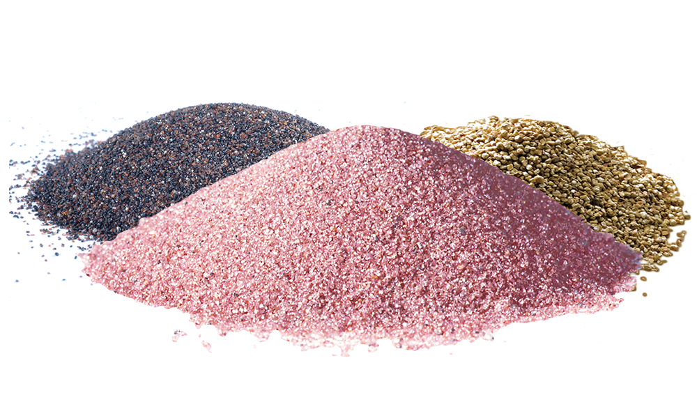
Jiangsu Henglihong Technology supplies aluminum oxide and titanium dioxide blasting media in SLA-grade specifications, with particle size distribution data, purity certificates, and process validation support documentation.
Request SLA Media Specifications & QuoteFiltres