Ceramic Bead Blasting PA12 Nylon SLS Parts: Depowdering and Surface Prep
PA12 nylon is the most widely processed material in commercial SLS production — and it demands a depowdering protocol precise enough to leave a clean, dimensionally accurate surface ready for dyeing, coating, or functional use. This guide provides a complete PA12-specific ceramic bead blasting protocol: which bead grade and size to select, how to set blast pressure by wall thickness and geometry, what surface finish results to expect, and how to prepare PA12 SLS parts for high-quality dyeing downstream.
1. PA12 SLS Surface Characteristics and Depowdering Challenges
Polyamide 12 (PA12) is the workhorse of commercial SLS production. Its low moisture absorption (less than 0.25% at equilibrium), broad chemical resistance, fatigue performance, and excellent dimensional stability make it the default specification for functional prototypes and end-use components in industrial, automotive, and consumer applications. Understanding what makes PA12’s post-build surface distinctive is the prerequisite to designing a depowdering protocol that consistently meets quality standards.
The PA12 powder and sintering environment
Commercial PA12 SLS powder — grades such as PA2200 (EOS) and comparable equivalents from major suppliers — has a median particle diameter (d₅₀) of approximately 50 to 60 µm, with the particle population spanning roughly 10 to 90 µm. During the build, the powder bed is maintained at approximately 165 to 168°C — close to, but deliberately below, PA12’s sintering onset temperature of around 170°C. The laser then selectively elevates specific zones above the sintering threshold, fusing those particles into the part geometry.
The zone immediately adjacent to each sintered layer — the powder particles that sit within a few hundred microns of the part surface but were not directly in the laser path — experiences elevated temperature without reaching full sintering. This partial thermal exposure bonds these surface-adjacent particles to the outer part wall, creating the semi-sintered skin: a layer of incompletely fused nylon that adheres firmly to the part surface and cannot be removed by compressed air alone.
Build-orientation effects on PA12 surface texture
The as-built surface texture of PA12 SLS parts varies significantly by orientation relative to the build direction:
- Horizontal surfaces (top faces, perpendicular to build direction): Ra typically 12–18 µm. Particle fusion is most complete here; the surface is visibly smoother.
- Vertical and angled side surfaces (parallel or at angle to build direction): Ra typically 20–28 µm. The staircase effect of layer-by-layer sintering is most pronounced on these faces, creating a distinctly textured, scale-like appearance.
- Downward-facing surfaces (within the powder bed during sintering): Ra typically 16–23 µm. Slightly smoother than upward side surfaces due to powder compaction, but still showing significant layer banding.
This build-orientation anisotropy — the visible surface texture difference between faces — is one of the defining characteristics of as-built SLS output. It is highly apparent on assembled parts with mixed face orientations, and is frequently the first quality issue that buyers of SLS parts notice. Ceramic bead blasting addresses this directly by reducing and homogenizing surface texture across all orientations.
Three categories of residual powder on PA12 SLS parts
After initial excavation from the build cake and compressed-air blow-off, three distinct categories of residual powder remain on PA12 SLS parts, each requiring different removal action:
- Loose unsintered powder in internal channels, recesses, and enclosed volumes — still free-flowing, removable by prolonged air blow-off or vibration, but often packed into narrow features that air alone cannot reach
- Caked unsintered powder in features that were under compression during the build — compacted but not sintered, requiring mechanical action to dislodge
- Semi-sintered surface skin on all external surfaces — bonded to the part, immune to air blow-off, requiring controlled mechanical impact from blasting media to break and remove
Ceramic bead blasting addresses all three categories simultaneously: the kinetic impact of beads entering internal channels dislodges loose and caked powder, while the blast action on external surfaces removes the semi-sintered skin and produces the final surface texture.
2. Why Ceramic Beads Are Ideal for PA12 SLS Powder Removal
The suitability of ceramic beads for PA12 SLS depowdering comes down to a specific set of material compatibility factors that other blasting media types cannot match simultaneously.
Hardness matched to PA12 substrate
PA12 sintered nylon has a surface hardness of approximately Shore D 75 to 80. Ceramic beads (ZS grade, Mohs 7 to 7.5) are hard enough to fracture the semi-sintered powder bond on the surface with each impact, but not so hard or dense that they erode the underlying fully sintered nylon in a single cycle. Angular abrasives such as aluminum oxide (Mohs 9) and steel grit (Mohs 7.5–8, density 7.8 g/cm³) carry too much impact energy for nylon substrates — they cut into the part surface, reduce dimensions rapidly, and leave a scratched rather than peened surface. Ceramic beads avoid this by combining moderate hardness with spherical geometry, converting kinetic energy into compressive impact rather than cutting force.
Chemical neutrality for dyeing operations
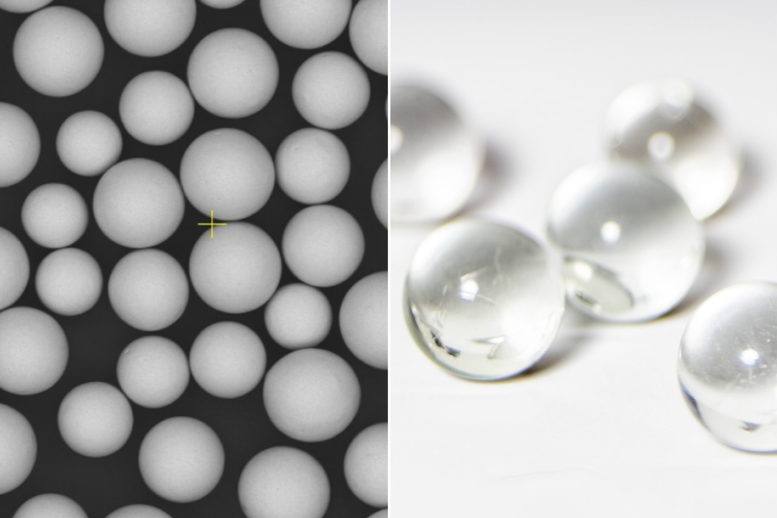
PA12 SLS parts destined for dyeing are especially sensitive to surface contamination. Metallic ions from degrading steel shot, silica fragments from fractured glass beads, and chromium compounds from certain coated media can all disrupt dye chemistry or create uneven uptake. Ceramic beads — whether ZrO₂ or ZS composition — are chemically inert at all temperatures encountered in SLS blasting. Their breakdown products remain ceramic particles with no reactive surface chemistry, leaving the PA12 surface uncontaminated and fully receptive to standard dye baths.
Recycling consistency through the media life cycle
PA12 SLS operations running at commercial scale process large numbers of parts per build cycle. Media that degrades rapidly — losing sphericity, shifting size distribution, generating angular fragments — produces variable surface finish output across builds, which adds Ra measurement burden and increases rework rates. Ceramic beads degrade gradually through spherical attrition, maintaining consistent surface finish output through the majority of their 1,500 to 4,000 cycle service life. This consistency is one of the primary reasons SLS bureaus that switch from glass beads to ceramic beads report reduced reject rates from surface finish failures.
For the full comparison of ceramic bead types and their properties in SLS depowdering, see the Ceramic Beads for SLS Powder Removal — Complete Guide.
3. Ceramic Bead Grade Selection for PA12 Applications
Two ceramic bead grades cover the full range of PA12 SLS depowdering applications: zirconia-silicate (ZS) for general production, and pure zirconia (ZrO₂) for the highest-volume or most demanding operations.
| Grade | Dichte (g/cm³) | Hardness (Mohs) | Recycling Cycles | Best PA12 Application | Cost Profile |
|---|---|---|---|---|---|
| Zirconia-Silicate (ZS) Standard | 3.8–4.0 | 7.0–7.5 | 1,500–2,500 | General PA12 production across all geometries; pre-dyeing blast | Moderate; best cost-per-part for mid-volume operations |
| Zirconia (ZrO₂) | 5.4–5.6 | 8.0–8.5 | 2,500–4,000 | High-volume PA12 lines; precision tolerance applications; finest Ra targets | Higher unit cost; lowest total cost-per-part at high throughput |
| Alumina-Silicate | 2.4–2.7 | 6.5–7.0 | 800–1,500 | Low-volume, simple geometry PA12 parts only | Low unit cost; higher long-run cost due to shorter life |
For most PA12 SLS operations, zirconia-silicate (ZS) beads are the recommended starting grade. They deliver effective semi-sintered skin removal, produce consistent Ra values across PA12 geometry types, and have a service life that justifies the unit cost premium over glass beads in all but the lowest-volume scenarios.
Upgrade to pure ZrO₂ beads when: your operation runs two or more shifts per day on PA12 builds; you need Ra values consistently below 6 µm; or you are processing PA12 parts for applications where CoC documentation of media composition is required (medical, aerospace).
Alumina-silicate beads are adequate for occasional low-volume PA12 depowdering of simple geometry parts but are not recommended for production environments where surface finish consistency and media management overhead matter.
4. Bead Size Selection by PA12 Part Geometry
Bead size controls both the surface finish Ra and the ability of the media to reach and clean internal features. For PA12 SLS parts, bead size selection is primarily driven by two factors: the target Ra for the part’s end use, and the smallest internal feature dimension that must be cleaned.
| Bead Size | Mesh Equiv. | PA12 Application | Expected Ra | Cycle Time (relative) |
|---|---|---|---|---|
| 0.05–0.10 mm | 150–270 | Channels <0.5 mm, fine lattice, ultra-smooth appearance parts | Ra 3–6 µm | Long (1.8–2.5×) |
| 0.10–0.15 mm | 100–150 | Complex geometry, channels 0.5–2 mm, walls 1–2 mm, pre-dye finish | Ra 4–7 µm | Moderate–Long (1.3–1.8×) |
| 0.15–0.25 mm Most Used | 60–100 | Standard PA12 production, moderate geometry, walls ≥2 mm | Ra 6–11 µm | Standard (1×) |
| 0.25–0.35 mm | 45–60 | Simple geometry, flat surfaces, coarse finish acceptable | Ra 9–16 µm | Short (0.65–0.8×) |
Channel access rule
The bead diameter must not exceed one-quarter of the smallest internal channel diameter that requires cleaning. For a 2 mm channel, use beads ≤ 0.5 mm; for a 1 mm channel, use beads ≤ 0.25 mm; for a 0.6 mm channel, use beads ≤ 0.15 mm. Beads larger than this limit will bridge the channel entrance — accumulating at the opening rather than entering and impacting the interior wall — leaving the channel interior unblasted and powder-filled.
Mixed-geometry builds
When a single PA12 SLS build contains parts with both fine-channel geometry and open flat-surface geometry, set the bead size for the finest feature that requires cleaning, and accept the longer cycle time this imposes on the open-surface parts. Blending two size fractions to try to serve both geometries in one cycle is generally counterproductive: the mixed charge produces a Ra value between the two grades and may not adequately penetrate the fine channels anyway.
Complete size selection reference with particle size distribution data, geometry-to-size mapping across all SLS materials, and internal channel sizing rules and worked examples.
5. Blast Pressure and Cycle Time Protocol for PA12
Blast pressure sets the velocity — and therefore the per-impact kinetic energy — of the ceramic beads striking the PA12 part surface. Too low, and the semi-sintered skin survives the blast; too high, and the nylon substrate erodes, dimensions shift, and fine features may deform. The protocol below is based on suction-feed blast cabinet operation; pressure-feed systems deliver higher velocity at equivalent inlet pressure and should be qualified at 10 to 15 PSI lower than the values shown to avoid over-blasting.
| PA12 Part Type | Minimum Wall / Feature | Blast Pressure (suction-feed) | Initial Cycle Time | Key Watch Points |
|---|---|---|---|---|
| Standard rigid PA12 | Wall ≥ 2.5 mm, no fine channels | 62–75 PSI | 5–9 min | Check open surfaces for even coverage |
| PA12 with moderate geometry | Wall 1.5–2.5 mm, channels 1–3 mm | 52–65 PSI | 7–13 min | Inspect fine features and channel exits mid-cycle |
| PA12 with fine channels | Wall ≥ 1.5 mm, channels < 1 mm | 42–55 PSI | 12–20 min | Verify channel exit powder in mid-cycle blow-down |
| PA12 thin-wall features | Wall 0.8–1.5 mm (body may be thicker) | 40–52 PSI | 8–16 min | Inspect thin walls for deformation or over-blast marks |
| PA12 lattice / porous structures | Strut diameter < 1.5 mm | 38–50 PSI | 10–18 min | Multiple short cycles preferred; rotate part between cycles |
Nozzle setup and standoff distance
For standard PA12 depowdering, set nozzle standoff distance at 75 to 120 mm. Shorter standoff (50–70 mm) concentrates impact and increases local cleaning intensity — useful for stubborn powder in deep recesses but requires careful control to avoid localised over-blasting on exposed edges. For parts with fine lattice structures or wall thicknesses below 1.5 mm, increase standoff to 100 to 150 mm to reduce peak impact energy while maintaining broad coverage.
Nozzle angle should be set perpendicular to the blast surface for maximum cleaning efficiency on flat faces. On parts with internal channels, angle the nozzle at 15 to 30° off-perpendicular to create a sweeping action inside the channel rather than a direct end-impact that simply packs powder deeper.
Mid-cycle inspection
For any new PA12 part geometry entering production, interrupt the first blast cycle at the halfway mark, remove the part from the cabinet, and inspect under bright directional light or with a 5× loupe. Check: (1) whether the semi-sintered skin is visibly broken across all external faces; (2) whether powder is still visible at channel exits or in recesses; (3) whether any thin-walled features show signs of deformation or white stress marks from over-impact. Adjust cycle time or pressure based on what you see, then complete the cycle. Document the qualified parameters for repeat production.
Full process optimization methodology for all SLS materials, nozzle selection guide, cycle time calculation worksheets, and process qualification templates.
6. PA12-GB Glass-Filled SLS Parts — Protocol Adjustments
PA12-GB — polyamide 12 filled with glass microspheres, typically at 20 to 40% fill by weight — is widely used in SLS for applications requiring higher stiffness and lower thermal expansion than unfilled PA12. Its surface behaves differently under ceramic bead blasting, requiring specific protocol adjustments.
Why PA12-GB needs a different approach
The embedded glass microspheres in PA12-GB significantly increase the surface hardness of the sintered part compared to unfilled PA12. The glass inclusions — typically borosilicate spheres of 15 to 50 µm diameter — are harder than the nylon matrix (Mohs ~5.5 vs. Shore D 75–80 for PA12) and create a composite surface that resists bead impact more effectively. Standard PA12 blast parameters applied to PA12-GB parts frequently leave the semi-sintered skin intact in areas where glass microspheres are densely concentrated near the surface.
Recommended PA12-GB protocol adjustments
PA12-GB blast parameter adjustments vs. standard PA12
- Increase blast pressure by 8–12 PSI above your standard PA12 setting for equivalent geometry
- Alternatively, step up one bead size class (e.g., from 0.15–0.25 mm to 0.20–0.30 mm) while maintaining the same pressure
- Extend cycle time by 20 to 35% compared to the PA12 baseline for the same geometry
- Use ZS or ZrO₂ beads only — alumina-silicate beads are too soft to reliably break the PA12-GB semi-sintered skin
Surface appearance after blasting PA12-GB
After ceramic bead blasting, the surface of PA12-GB parts looks and feels different from unfilled PA12. The glass microspheres at or near the part surface become exposed or partially exposed during the blast, creating a mildly sparkle-textured appearance with higher Ra (typically Ra 10 to 18 µm after blasting) compared to unfilled PA12 at equivalent bead size. This is normal and expected. The surface is clean and ready for its intended application, but the aesthetic texture of PA12-GB blasted parts should be evaluated against customer expectations before production qualification — it differs noticeably from the uniform matte finish of blasted PA12.
PA12-GB parts are generally not suitable for high-quality dyeing due to the glass bead surface inclusions interfering with dye penetration. If dyeing is required on a glass-filled SLS part, discuss the surface quality implications with your customer before committing to a specific protocol.
7. Surface Finish Results: Ra Values Before and After Blasting
The primary measurable outcome of ceramic bead SLS depowdering is surface roughness reduction and homogenisation. The following data represents results from standard PA12 SLS builds (PA12 powder, standard build parameters, 100 µm layer thickness) processed with ZS ceramic beads in a suction-feed cabinet.
| Surface Orientation | As-Built Ra (µm) | ZS 0.15–0.25 mm / 62 PSI / 7 min | ZS 0.10–0.15 mm / 52 PSI / 10 min | ZrO₂ 0.10–0.15 mm / 55 PSI / 8 min |
|---|---|---|---|---|
| Horizontal (top face) | 12–17 | 5–8 | 4–6 | 3–6 |
| Side / angled surface | 20–27 | 7-12 | 5–9 | 5–8 |
| Downward-facing (in-bed) | 16–22 | 6–10 | 5–8 | 4–7 |
Surface uniformity improvement
The Ra reduction numbers above do not fully capture the most commercially important outcome: the improvement in surface uniformity across build orientations. On as-built PA12 SLS parts, the Ra difference between horizontal and angled side surfaces is typically 8 to 12 µm — clearly visible and tactile. After ceramic bead blasting, this difference reduces to 2 to 5 µm, which is far less apparent to the eye and touch. Parts that appeared to have a two-zone surface texture as-built (smoother on top, rougher on sides) achieve a far more visually uniform appearance after blasting, even if the absolute Ra on each surface differs slightly.
This homogenisation effect is particularly important for large flat-panel PA12 parts (covers, housings, enclosures) where mixed-orientation faces are visible in the assembled product. For these parts, the appearance uniformity improvement from ceramic bead blasting is often the primary driver — more so than the absolute Ra value reached.
Comprehensive Ra and Rz datasets across bead grades and process conditions, surface profile images showing before/after comparison, and measurement protocol templates for production QC.
8. Dimensional Accuracy and Material Removal on PA12 SLS Parts
Ceramic bead blasting removes material from PA12 SLS parts — but in controlled, measurable, and generally negligible quantities relative to the dimensional tolerances of most SLS applications.
What is actually removed
The material removed during a ceramic bead blast cycle consists primarily of the semi-sintered surface skin, not the fully sintered bulk PA12 substrate. The semi-sintered skin has lower density and cohesive strength than the interior sintered structure, and it debonds from the surface under bead impact rather than the surface itself being eroded. The actual material removal from the fully sintered part body is typically in the range of 15 to 40 µm per external surface per standard blast cycle — a fraction of the surface skin thickness.
Material removal data by protocol
| Bead Grade / Size | Blast Pressure | Cycle Time | External OD Removal (µm/surface) | Internal ID Removal (µm/surface) |
|---|---|---|---|---|
| ZrO₂ 0.15–0.25 mm | 65 PSI | 7 min | 25–60 | 8–20 |
| ZS 0.15–0.25 mm | 62 PSI | 7 min | 20–52 | 7–18 |
| ZS 0.10–0.15 mm | 52 PSI | 10 min | 10–32 | 4–12 |
| ZS 0.10–0.15 mm | 45 PSI | 12 min | 8–22 | 3–9 |
Tolerance implications for PA12 SLS parts
Standard SLS PA12 production tolerances are typically ±0.2 to ±0.3 mm for dimensions up to 100 mm. At these tolerance levels, even the maximum material removal in the table above (60 µm) represents less than one-third of the tolerance band — well within the budget. For tighter-tolerance PA12 applications (±0.1 mm or better), specify the fine-bead protocol (0.10–0.15 mm, 45–52 PSI) and verify on a first-article blast sample before entering production.
Internal dimensions (holes, channels, mating recesses) consistently show lower material removal than external dimensions — typically 30 to 50% of the external value — because the blast plume has limited access to internal features and loses energy before reaching all internal walls. Design compensation, if required, should therefore be applied primarily to external OD dimensions rather than internal bores or channel diameters.
Full material removal dataset, OD/ID comparison, design compensation guidelines, and first-article measurement protocol for precision SLS applications.
9. Preparing PA12 SLS Parts for Dyeing After Ceramic Bead Blasting
PA12 SLS parts are routinely dyed using hot-bath acid dyes or dedicated PA nylon dye formulations to achieve black, grey, and a range of colour outputs. The pre-dye surface condition — specifically the surface microstructure left by ceramic bead blasting — directly controls how evenly and deeply dye is absorbed, and is the single most important factor in achieving consistent batch colour.
How ceramic bead blasting improves dye uptake
As-built PA12 SLS parts have a heterogeneous surface structure: dense, fully sintered zones alternate with more porous, partially sintered areas. These zones absorb dye at different rates, producing colour variation that is most visible on large flat surfaces under raking light. Even a clean as-built part with the loose powder removed by air blow-off only — but without bead blasting — will show this dye heterogeneity.
Ceramic bead blasting removes the heterogeneous semi-sintered surface layer and mechanically opens the PA12 surface microstructure uniformly. Post-blast, the part surface presents a consistent array of micro-scale pores and surface asperities — an even, reproducible texture that absorbs dye at a uniform rate across all build-orientation faces. The visual result is dramatically more consistent colour, with reduced patch variation and improved batch-to-batch repeatability.
Bead size effect on colour depth
There is a measurable relationship between blast surface Ra and dye colour depth:
- Finer beads (0.10–0.15 mm) → lower Ra (4–7 µm) → lighter, more pastel dye result — the smoother surface has less exposed micro-porosity per unit area, limiting dye penetration depth
- Coarser beads (0.15–0.25 mm) → higher Ra (7–11 µm) → deeper, more saturated dye result — the rougher surface exposes more surface area and micro-porosity, allowing greater dye uptake
This relationship can be used as a process control lever: if a specific dye formulation is producing colour that is consistently lighter than the target, switching from 0.10–0.15 mm to 0.15–0.25 mm beads will deepen the colour without changing the dye bath chemistry. Conversely, if colour is too dark or saturated, moving to finer beads and a smoother surface finish lightens the output.
Recommended pre-dye blast protocol for PA12
- Bead grade: ZS, 0.10–0.20 mm
- Blast pressure: 48–60 PSI
- Cycle time: 6–12 minutes (adjust to Ra 5–9 µm)
- Post-blast: Blow off media residue with clean compressed air; inspect for residual powder in recesses
- Timing: Transfer to dye bath within 4 hours of blasting; avoid prolonged exposure to high-humidity environments between blasting and dyeing
Pre-dyeing blast protocols, colour uniformity measurement methodology, bead-size-to-colour-depth relationship data, and batch colour calibration guide for PA12 SLS dyeing operations.
10. Common Process Errors in PA12 SLS Ceramic Bead Depowdering
Even with the right bead grade and size specified, PA12 SLS depowdering failures in production typically trace back to a small number of recurring process errors. Understanding these in advance prevents the majority of rework and reject events.
Error 1 — Over-blasting at high pressure
Running at the maximum blast pressure for a given part type, or extending cycle time well beyond the qualified value, removes more material than necessary. On PA12, over-blasting manifests as elevated Ra beyond the target, visible surface texture that looks abraded rather than evenly matte, and dimensional reduction at sharp edges. It also accelerates bead degradation, increasing media cost per part. The corrective action is to establish and strictly follow the qualified pressure and cycle time, rather than using “more blast” as a substitute for process qualification.
Error 2 — Incomplete depowdering due to undersized cycle time
Short-cutting the cycle to increase throughput is the most common source of PA12 depowdering rejects. The tell-tale is a part that looks largely clean but retains a slightly dusty, less uniform texture on internal channels and in corners — visible under raking directional light. These parts often pass a quick visual check but fail when subjected to proper Ra measurement or when the retained powder becomes visible after dyeing.
Error 3 — Wrong bead size for the channel geometry
Using 0.15–0.25 mm beads on a PA12 part with 0.6 mm internal channels means the beads bridge the channel entrance and never enter. The channel interior is never blasted. The error is easy to miss visually because the channel appears dark and possibly powder-filled, which can be mistaken for acceptable shadow. Check channel sizing against the one-quarter-of-channel-width bead sizing rule every time a new part design is introduced.
Error 4 — Neglecting media charge monitoring
An aging media charge that has not been topped up produces gradually degrading surface finish output — higher Ra, less uniform texture, and increasing cycle times needed to achieve adequate cleaning. In production operations, this degradation is often gradual enough not to trigger an immediate reject but accumulates into batch-level surface quality variation that becomes a customer complaint. Monthly sieve analysis and Ra tracking with a reference coupon prevents this from occurring.
Error 5 — Contaminated media from nylon powder accumulation
In high-volume PA12 operations, blasted-off nylon powder accumulates in the media charge. The powdered nylon partially coats the bead surfaces, reducing their cleaning effectiveness and causing them to clump in the blast hose feed. If the blast cabinet appears to be delivering less consistent flow than usual, or if parts show patchy rather than even surface coverage, media contamination is a likely cause. Partial replacement of 20 to 30% of the charge with fresh media resolves this without requiring full charge replacement.
Häufig gestellte Fragen
For the finest surface finish, use zirconia-silicate beads in the 0.10 to 0.15 mm range at 48 to 55 PSI. This combination typically achieves Ra 4 to 7 µm — the smoothest result achievable with standard dry ceramic bead blasting — and is particularly suited for appearance-grade PA12 parts and those destined for dyeing. For general production parts where Ra 7 to 11 µm is acceptable, the 0.15 to 0.25 mm range delivers faster cycle times at equivalent or higher pressure, making it the better choice for throughput-sensitive operations. The fine-bead option adds 30 to 60% to cycle time compared to the standard range, so reserve it for parts where the Ra target genuinely requires it.
No — PA12-GB requires a modified protocol. The glass microsphere fillers in PA12-GB significantly increase surface hardness compared to unfilled PA12, meaning the standard PA12 protocol frequently leaves semi-sintered powder intact in glass-bead-dense surface areas. For PA12-GB, increase blast pressure by 8 to 12 PSI above your standard PA12 setting, or step up to the next coarser bead size class (for example, from 0.15–0.25 mm to 0.20–0.30 mm) while maintaining the same pressure. Extend cycle time by 20 to 35% compared to your PA12 baseline for the same geometry. Note that PA12-GB surface finish Ra after blasting (typically Ra 10 to 18 µm) is higher than unfilled PA12 due to the glass bead surface exposure — this is normal and expected.
For a medium-complexity PA12 part of 50 to 150 cm³ build volume using ZS beads at 0.15 to 0.25 mm and 60 to 65 PSI in a suction-feed cabinet, a typical production cycle runs 5 to 9 minutes. Parts with fine internal channels (below 1.5 mm) processed with 0.10 to 0.15 mm beads at reduced pressure may run 12 to 20 minutes. Simple flat-surface geometry parts at the upper end of the pressure range can be completed in 4 to 6 minutes. First-article qualification establishes the correct cycle time baseline for each unique part design — that qualified value should be documented and maintained in production rather than adjusted based on operator judgment cycle to cycle.
Standard ceramic bead SLS depowdering at qualified parameters does not meaningfully affect the bulk tensile strength, flexural modulus, or elongation at break of PA12 SLS parts. The blast process removes only the semi-sintered surface skin and a small amount of surface material — 15 to 55 µm per external surface per standard cycle — while leaving the fully sintered interior structure intact. The mechanical properties of PA12 SLS parts are determined by the build parameters and powder properties, not by the post-build surface treatment. For fatigue-critical PA12 parts, the compressive residual stress introduced at the part surface by ceramic bead peening can modestly improve fatigue resistance — an incidental benefit for applications where surface fatigue initiation is a concern.
Related Articles in This Series
This guide is part of a complete series on ceramic bead blasting for SLS powder removal. Return to the Ceramic Beads for SLS Powder Removal — Complete Guide for the full overview, or explore other material-specific and process guides below.
Specify Ceramic Beads for Your PA12 SLS Depowdering Line
Jiangsu Henglihong Technology Co., Ltd. supplies zirconia and zirconia-silicate ceramic blasting beads in ISO-classified sizes from 0.05 mm to 0.60 mm. Tell us your PA12 part geometry, wall thickness, and Ra target — we will recommend the right grade, size, and starting protocol, with samples available for first-article qualification.
Request Samples & Technical SupportFilter