Plastic Media Blasting: Step-by-Step Setup Guide
Plastic media blasting delivers consistently excellent results when the equipment is set up correctly and the operator understands the process variables that govern it. It delivers frustrating, inconsistent, or damaging results when those same variables are ignored. The difference between a well-run plastic blast operation and a poorly-run one is not exotic equipment or expensive media — it is disciplined setup, calibrated parameters, and systematic process control applied from the first blast forward.
This guide is a complete, practical setup reference for anyone starting, overhauling, or troubleshooting a plastic media blasting operation. It covers the entire process in sequence: selecting and sizing equipment, choosing media and verifying it, dialing in blast parameters, setting up for the specific substrate, running the first qualification blast, and maintaining consistent results in production. Whether you are setting up a cabinet-based restoration operation, a production blast room for automotive stripping, or an aerospace depaint facility, the underlying setup logic is the same — and this guide covers all of it.
For media type selection before you begin setup, see: Plastic Blast Media Types Compared: Urea vs Melamine vs Acrylic.For a broader overview of the full plastic media category, see: What Is Plastic Media? The Complete Guide.
What You Need Before You Start
Before any equipment arrives on site, clarify four things that determine every downstream setup decision:
🎯 Define Your Substrate and Objective
- What material are you blasting? Steel, aluminum, composite, mold tool — each has different media and pressure requirements
- What are you removing? Paint, coating, rust, flash, contamination — determines media aggressiveness
- What must the surface look like after? Bare metal, specific Ra, retained surface finish — determines media mesh and process control requirements
- Will parts go directly to coating, plating, or assembly? Determines how critical surface cleanliness and contamination control must be
📐 Define Your Scale and Throughput
- Part size: Determines whether you need a blast cabinet, blast room, or portable equipment
- Parts per day: Determines compressor sizing and whether media reclaim is economically justified
- Batch vs. continuous: Batch operations (load, blast, unload) vs. continuous-feed setups have different equipment implications
- Indoor vs. outdoor: Outdoor blasting has regulatory, wind, and containment considerations that indoor setups avoid
The compressor must deliver adequate CFM (cubic feet per minute) of air at the target nozzle pressure — continuously, not just at startup. This is the constraint that most operators underestimate. Compressor specifications list peak 或 displacement CFM, not sustained delivery at operating pressure. The number that matters for blast operations is FAD (Free Air Delivery) at the target pressure — often 30–50% lower than the rated peak CFM.
CFM Requirements by Nozzle Size
These are the sustained CFM requirements at nozzle inlet — not at the compressor outlet. Account for 10–15% pressure drop across 50 feet of hose at blast flow rates:
Compressor Type by Application
| Application Scale | Nozzle Size | Recommended Compressor | HP Range |
|---|---|---|---|
| Cabinet blasting, small parts, mold cleaning | 3/16″–1/4″ | Reciprocating piston, single or two-stage | 5–10 HP |
| Automotive panel stripping, medium cabinets | 1/4″–5/16″ | Rotary screw, continuous duty | 10–20 HP |
| Full-vehicle strip, small blast rooms | 5/16″–3/8″ | Rotary screw, industrial | 25–40 HP |
| Production blast rooms, aerospace depaint | 3/8″–1/2″ | Rotary screw, industrial; or towable diesel | 50–100 HP |
| Large-scale industrial / depot operations | 1/2″–5/8″ | Multiple compressors or large central plant | 100+ HP |
Air Quality Requirements
Plastic media blasting requires dry, clean air. Moisture in the air supply causes media clumping, erratic blast flow, and — critically — moisture contamination of the blasted substrate before coating. Install an aftercooler, a refrigerated air dryer, and a coalescing filter downstream of the compressor. For large operations, a desiccant dryer downstream of the refrigerated dryer achieves dew points below 40°F at the nozzle, eliminating moisture-related process failures. Check the filter/separator bowl daily; drain if accumulated liquid is present.
Blast Cabinet
Blast cabinets are self-contained enclosures with a window, gloves, internal lighting, and an integral media collection hopper. They are ideal for small-to-medium parts that fit through the cabinet door — electronics deflashing, mold cleaning, small automotive components, prototype parts finishing. Cabinets with suction-feed systems are suitable for light plastic media at low pressures. Pressure-pot-fed cabinets provide higher blast energy and are better suited for coating removal applications. When selecting a cabinet for plastic media, verify that the dust collector is sized for the finer particle density of plastic media dust (a collector rated for sand will typically suffice, but confirm the filter micron rating — 5-micron absolute minimum for plastic media dust).
Pressure Blast Pot
A pressure blast pot is a sealed pressure vessel that holds blast media and pressurizes it to the operating pressure, feeding media and air to the blast nozzle through a single hose. This is the most efficient blast delivery system and the standard for all serious plastic media applications — automotive stripping, aerospace depainting, mold cleaning, industrial applications. Pots range from small portable 1.5-cubic-foot units to large 6-cubic-foot production pots mounted on wheeled frames. Key installation steps:
- Position the pot on a level surface within the blast area — pot must be upright to prevent media bridging
- Connect the air inlet to the compressor with minimum 3/4-inch ID hose; use 1-inch ID for runs over 50 feet
- Set the inlet regulator to 10–15 PSI above target nozzle pressure to provide headroom for pressure drop across the hose and metering valve
- Install an inline moisture separator between the compressor and the pot inlet
- Test the remote deadman control (the safety valve that stops blast when the operator releases the handle) before first use — this is a life-safety device
Blast Room
A blast room is an enclosed room-sized space designed for blasting large parts or assembled vehicles. Walls and ceiling are lined with rubber or polyurethane panels to absorb blast energy and protect the structure. The floor has a recovery system (typically a reclining floor with auger or pneumatic conveyor) to collect spent media and debris for reclaim or disposal. Blast rooms must have designed ventilation — typically 60–100 air changes per hour — to maintain operator visibility and OSHA dust exposure compliance. For plastic media blast rooms, the ventilation must handle the finer, lighter plastic media dust that stays airborne longer than mineral abrasive dust.
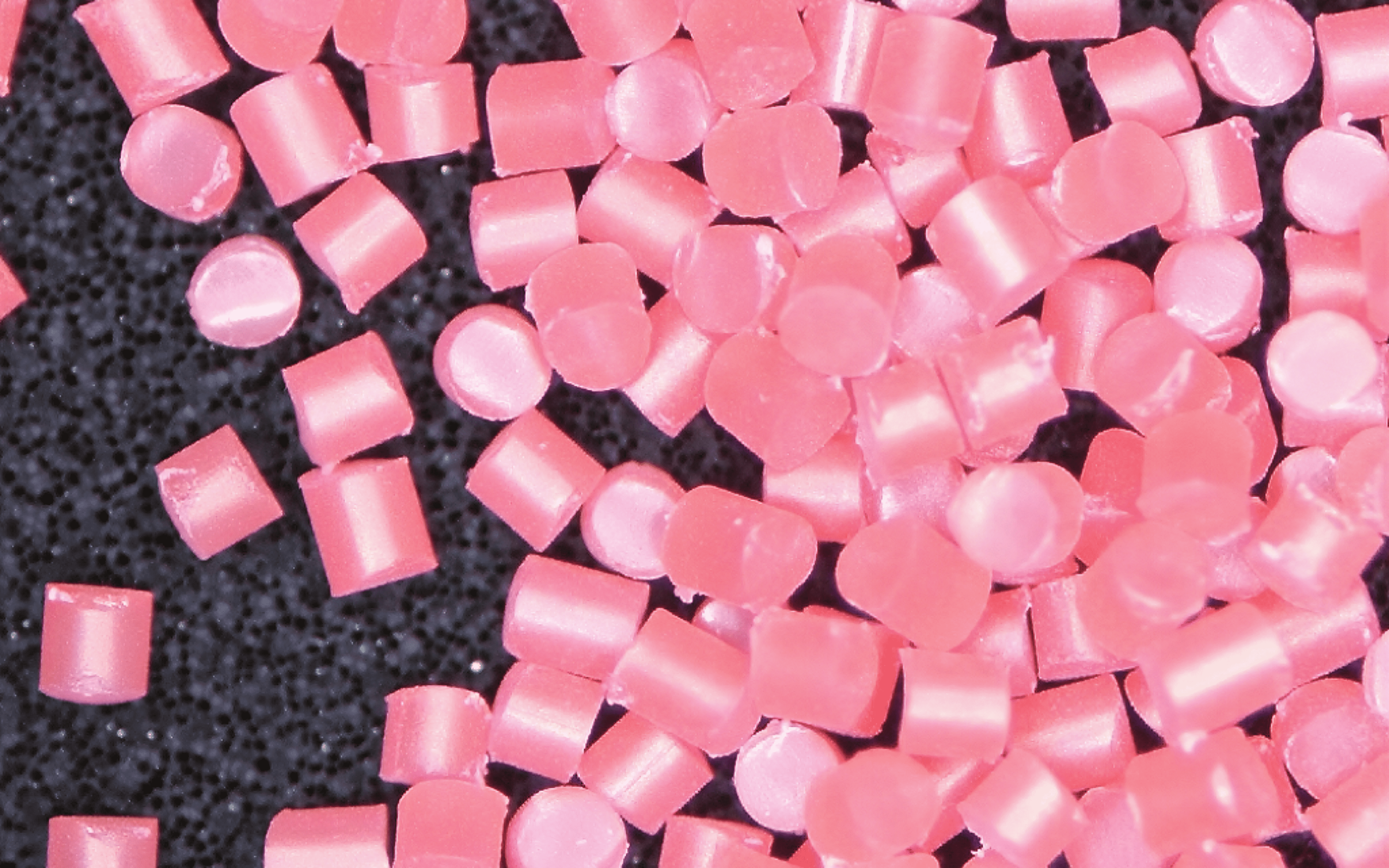
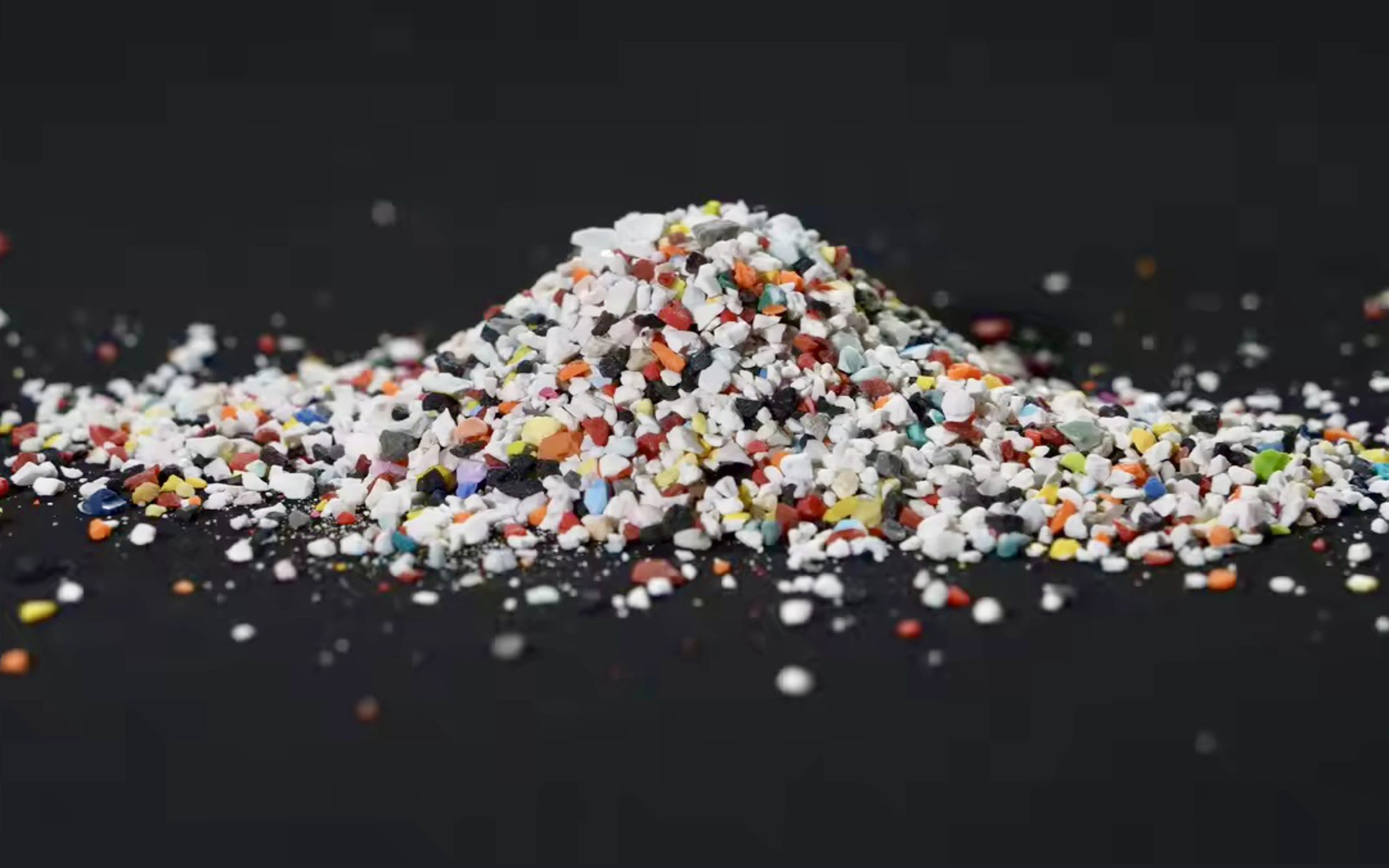
Media Type Quick Reference
| 媒体类型 | Mohs | Best For | Avoid On |
|---|---|---|---|
| Type II Urea Formaldehyde | ~3.5 | Aluminum aircraft structure, automotive steel panels, general coating removal — the most-used type | CFRP composites, optical mold cavities, electroless nickel plating |
| Type III Melamine Formaldehyde | ~4.0 | Harder coatings, rubberized underseal removal, titanium, steel chassis | Aluminum aircraft skin at structural pressure limits, soft mold materials |
| Type V Acrylic (PMMA) | ~3.0 | CFRP composites, polished mold cavities, electronics deflashing, anodized aluminum, beryllium copper | Applications requiring fast strip rate on hard coatings |
Mesh Size Selection
Mesh size is the particle size specification, expressed as the mesh screen count that the particles pass through or are retained on. Lower mesh numbers = larger particles = more aggressive cutting action and faster strip rate. Higher mesh numbers = smaller, finer particles = gentler action, better surface finish, but slower strip rate. Select mesh based on the coating thickness being removed and the surface finish required after blasting:
| Application | Mesh Size | 原因 |
|---|---|---|
| Heavy coating removal, thick paint, underseal | Mesh 16–20 | Larger particles carry more impact energy per hit; faster removal of thick, tenacious coatings |
| Standard automotive paint strip (3–8 mil total) | Mesh 20–30 | Balanced strip rate and surface finish; most common for general automotive and aerospace depaint |
| Aerospace aluminum, sensitive substrates | Mesh 30–40 | Finer particle = lower impact energy per hit = better protection for thin aluminum skins |
| Mold cleaning, pre-anodize finishing | Mesh 50–60 | Very gentle action; surface finish preservation priority over strip rate |
| Electronics deflashing, optical surfaces | Mesh 60–80 | Finest available; minimum possible impact energy; used where substrate damage tolerance is essentially zero |
Incoming Lot Verification
Before loading any media into your blast pot, perform three quick verification checks on the incoming lot:
- Visual check: Media should be free-flowing with no clumping. Clumped or caked media indicates moisture absorption during storage — do not use until dried at 100–120°F for 2–4 hours and re-tested for flow
- Moisture test: Take a small handful and squeeze firmly. If it compacts and holds shape when the hand opens, moisture content is too high. Dry, in-spec media should flow freely from the open hand
- Certificate of Conformance: For aerospace, defense, and other regulated applications, verify the lot CoC references each required MIL-P-85891A test parameter with actual measured values. Retain with your work order records
Nozzle Bore Selection
The nozzle bore diameter determines the blast stream width and CFM requirement. For plastic media blasting, the most common nozzle sizes are 3/16 inch to 1/2 inch bore. Smaller bores provide more precise media placement for detail work (mold cleaning, electronics, aerospace spot repair). Larger bores provide higher throughput for large-area coating removal.
Nozzle geometry also matters: straight-bore nozzles provide the highest velocity and most focused stream, suitable for aggressive coating removal. Venturi nozzles — which flare from a constriction to a wider exit — draw in additional air at the flare exit, increasing media velocity beyond what the inlet pressure alone provides. Venturi nozzles increase strip rate 40–60% compared to straight-bore at the same inlet pressure and are standard for production blast work.
Nozzle Material for Plastic Media
Plastic media is significantly less abrasive to nozzle material than mineral abrasives. Standard boron carbide nozzles — which last 200–300 hours with sand — can last 500–1,000 hours or more with plastic media. Tungsten carbide nozzles are also acceptable. Do not use ceramic or standard cast iron nozzles — the lower wear resistance produces faster bore growth, more frequent calibration drift, and higher replacement frequency than the cost savings justify.
Pre-Use Nozzle Inspection
Before each shift, inspect the nozzle bore with a nozzle wear gauge (a calibrated pin gauge sized to the maximum acceptable bore diameter). Record the measurement. A new 3/8-inch nozzle measures exactly 0.375 inch — replace when bore reaches 0.4375 inch (1/16-inch oversize). Worn nozzles are the single most common source of undetected parameter drift in blast operations:
Plastic media blasting generates two categories of airborne dust that require capture: fractured media particles (the fines produced as media pieces break apart during blast impact) and coating residue dust (paint, primer, and rust particles removed from the substrate). Both categories are respiratory hazards; coating residue may carry additional regulatory requirements depending on the coating chemistry (chromate primers, lead-based paint, isocyanate-containing topcoats).
Dust Collector Sizing
Size the dust collection system to maintain a minimum air velocity of 100 feet per minute at all capture points — enough to prevent dust from settling inside ductwork. For blast cabinets, the collector typically mounts to the cabinet’s integral exhaust port with a factory-specified CFM rating; verify it is appropriate for the media being used (some collectors specified for mineral abrasive are under-powered for plastic media’s finer dust). For blast rooms, the collector must process enough air to achieve 60–100 room air changes per hour — calculate as room volume (cubic feet) × 60 to 100 / 60 = required CFM.
Filter Selection
For plastic media blast dust, specify cartridge filters rated at minimum 5 microns absolute, with MERV-14 or better for applications involving chromate primer or heavy metal coatings. Pulse-jet self-cleaning cartridge collectors are the most practical choice for production blast operations — they maintain consistent airflow without manual filter cleaning intervals. Replace filter elements when pressure differential across the filter exceeds the manufacturer’s maximum (typically 6–8 inches water column) — operating with a loaded filter both reduces airflow below the capture threshold and forces dust-laden air around the filter seals.
Plastic media blast operations involve high-velocity particle streams, dust concentrations that can impair visibility in minutes, and potential exposure to the coating materials being removed. PPE is not optional — it is the last line of protection between the operator and the hazards inherent to the process.
Masking is not a secondary concern — it is a primary quality control step. The blast stream reaches surfaces at 3–6 feet from the target area, and the damage it does to unprotected adjacent surfaces (glass etching, rubber erosion, sensor damage) cannot be undone. The five minutes spent masking correctly prevent hours of rework.
Masking Materials by Surface Type
| Surface to Protect | Masking Method | Notes |
|---|---|---|
| Glass (windows, lenses) | 3 layers heavy kraft paper + 18″ rigid cardboard or plywood overlay | Masking tape alone is insufficient — blast will penetrate. Rigid backing essential. For blast rooms, use rubber sheet or polyurethane foam board over paper |
| Rubber seals and weatherstrip | Remove before blasting; if not removable, mask with dense foam + rigid backing | Blast embeds media in rubber. Once embedded, media particles cause slow deterioration of the seal over time. Removal is strongly preferred |
| Exposed sensors and electronics | Remove or cap with dedicated plugs; cover with rigid backing | Never rely on tape alone for electronic components. A single media particle in a sensor port can cause intermittent failures months after the blast operation |
| Painted surfaces adjacent to blast area | Paper + foam board; extend 12″ beyond blast area perimeter | Overspray from plastic media at 40 PSI can etch and dull adjacent painted surfaces at 4–5 foot range |
| Chrome plating | Remove plated components or mask with rubber sheet + rigid backing | Plastic media will not remove hard chrome at standard blast parameters but will dull the surface; if chrome removal is not the intent, protect it |
| Threaded bores and ports | Install threaded plugs; cap with expanding foam backer rod | Media embedded in thread forms causes galling during reassembly. Plug every threaded feature before blast, without exception |
Three parameters govern blast effectiveness and substrate safety in plastic media blasting: nozzle pressure, standoff distance, and impingement angle. Every other variable — strip rate, surface profile, edge damage risk — is a function of these three. Set them correctly for your specific substrate, and everything else follows. Set them incorrectly, and no amount of technique compensates.
Pressure: Measure at the Nozzle, Not the Regulator
Install an inline gauge at the nozzle inlet — not at the blast pot regulator and not at the compressor. Pressure drop across the blast hose (from the pot to the nozzle) at high blast flow rates is typically 5–15 PSI depending on hose length, diameter, and flow rate. A regulator set to 45 PSI at the pot may deliver only 32 PSI at a nozzle 50 feet away — putting you 13 PSI below the intended operating parameter without any indication at the control point. Measure where it matters: at the nozzle inlet.
Standoff Distance
Standoff distance is the gap between the nozzle exit and the part surface. Increasing standoff reduces impact energy (the particle decelerates in air after leaving the nozzle) and widens the blast pattern. Decreasing standoff concentrates energy on a smaller area and increases strip rate — but at the risk of localized over-blasting if nozzle movement is not consistent. The practical standoff range for most plastic media applications is 6–12 inches:
- 6–8 inches: Maximum effectiveness for coating removal; requires consistent nozzle motion; suitable for experienced operators
- 8–10 inches: Best balance of strip rate and substrate protection; default for most applications
- 10–14 inches: Reduced strip rate but maximum substrate protection; use on thin aluminum, composite structures, and detail areas requiring lower impact energy
Impingement Angle
The impingement angle is the angle between the blast stream centerline and the part surface. Ninety degrees (perpendicular) delivers maximum impact energy and fastest strip rate on flat surfaces. Angles below 90° produce a tangential cutting action that is more effective on surfaces where the coating must be undercut from the edges — thick carbon deposits, heavily bonded primer — and reduces the risk of media embedment on soft substrates. For general coating removal on steel: 75–85°. For aluminum and composites: 65–80°. For mold cleaning and detail work: 60–75°.
Before blasting any production part or primary structure, run a qualification blast on a representative test area. For automotive work, this is typically a small hidden panel section — an inner door area, the underside of a hood lip, or an inner wheel arch. For aerospace, it is a non-flight-critical area of the same substrate material. For mold cleaning, it is a non-cavity area on the back face of the mold.
Qualification Procedure
- Blast a 4 × 4 inch test area at your target parameters for the same duration you expect to use on the production surface
- Inspect immediately under good raking light: is the coating removed completely? Is the substrate visible beneath with a consistent, matte, uniform appearance?
- Check for damage indicators: Warping (run your hand across the surface — any deflection indicates excessive blast energy), directional scoring, or discoloration of the substrate
- Measure surface profile with Testex Press-O-Film replica tape if your application has a profile specification. Compare to the specified range
- Adjust if needed: If coating is not fully removed at target parameters, increase pressure in 3 PSI increments — not 10 PSI jumps — and re-test. If substrate damage is visible, reduce pressure before proceeding to production
What a Good Qualification Result Looks Like
A correctly qualified blast area on steel shows: completely removed coating revealing a clean, matte grey steel surface with a light, even texture and no directional grinding marks. The surface should have a chalky, slightly rough appearance — not shiny (which would indicate the coating was not fully removed) and not deeply scored (which would indicate excessive blast energy). On aluminum, the correctly blasted surface shows a uniform, slightly rough matte finish with no tool marks from the original machining, no streaks, and no shiny spots indicating missed coverage.
The surface produced by plastic media blasting is chemically active bare metal — more reactive than an unmachined surface because the blast process has removed the natural oxide layer and created a fresh, high-energy surface. That reactivity is what makes blast-prepared surfaces bond so well to coatings — and also what makes them susceptible to rapid re-oxidation and flash rusting if not immediately protected. Post-blast procedures are not optional follow-up steps; they are integral parts of the process that determine whether the blast work produces the coating performance it was designed to enable.
Immediate Post-Blast Sequence
- Compressed air blow-off: Use a clean, dry air blow gun at 80–100 PSI to remove all media particles, coating debris, and dust from every surface. Work from the highest point downward, covering all features, pockets, and recesses. Any media particle left on the surface will be sealed under the coating and become a corrosion nucleus.
- Visual inspection: Inspect the blown-off surface under strong raking light. Any residual coating shows as a gloss contrast against the matte blast surface — spot-treat remaining coating areas before the overall surface oxidizes.
- IPA wipe (optional but recommended): A light wipe with isopropyl alcohol on a lint-free cloth removes dust residue and any oil contamination from hands or tools. Do not use acetone, lacquer thinner, or MEK — these solvents are too aggressive and may re-deposit contamination from the cloth onto the bare surface.
- Apply primer within 4 hours (steel): For bare steel, apply the first coat of primer — typically 2K epoxy primer — within 4 hours of blast completion in normal shop conditions. In humidity above 70% RH or temperature above 80°F, reduce this window to 2 hours. Flash rust that appears on the surface before priming must be removed — it cannot be primed over — requiring a second blast cycle and resetting the clock.
- Apply primer within 2 hours (aluminum): Bare aluminum begins oxidizing immediately. For applications where the oxide layer thickness matters (anodizing, plating, precision coating), the window between blast completion and first surface treatment is shorter than for steel. Apply etch primer, conversion coating, or transfer to the anodize/plate line within 2 hours.
Setting Up Media Reclaim
Media reclaim systems recover used plastic blast media, separate it from coating debris and broken media fines, and return usable media to the blast pot for reuse. For any operation consuming more than approximately 50 pounds of media per week, a reclaim system reduces effective media cost by 60–80% and is typically recovered in media savings within the first month of operation.
The reclaim system operates in three stages: mechanical collection (floor sweep, auger conveyor, or vacuum recovery system moves used media from the blast floor to the reclaim unit), air wash separation (an upward air current at calibrated velocity removes lightweight coating dust and fines while allowing heavier, intact media particles to fall through to the clean media hopper), and screen classification (a vibrating screen removes oversize particles and confirms that remaining media is within the target mesh size range before returning it to the blast pot).
The most common failure mode in media reclaim systems is the air wash calibration. Set too low, coating debris and broken media fines pass through to the clean media hopper — loading the blast pot with contaminated media that produces poor surface results and clogs nozzles. Set too high, intact usable media is carried over with the debris stream — reducing media recovery rate and increasing the volume of waste requiring disposal. Calibrate the air wash velocity for your specific media type and mesh size: the correct velocity is just above the terminal velocity of the intact media particles and just below the velocity that would carry over the coating debris. Most reclaim manufacturers provide calibration charts for their systems by media type — use them as the starting point and verify with a test run before production.
Nozzle Wear: Monitoring and Replacement Schedule
Nozzle wear is the parameter drift source that most operators discover too late. A worn nozzle operating at the “correct” compressor setting is actually delivering under-pressure, widened-pattern blast at the part surface — producing lower strip rates, requiring longer cycle times, and potentially producing an uneven surface profile. Because the operator sees the same gauge reading at the pot, there is no visible indication that anything has changed. Only nozzle bore measurement reveals the drift.
| Nozzle Bore (nominal) | Replace at (max bore) | Typical wear interval with plastic media | Action at replacement trigger |
|---|---|---|---|
| 3/16″ (0.1875″) | 0.250″ (+1/16″ oversize) | 300–600 hours | Replace immediately; do not operate with over-worn nozzle |
| 1/4″ (0.250″) | 0.3125″ (+1/16″ oversize) | 400–700 hours | Replace immediately |
| 5/16″ (0.3125″) | 0.375″ (+1/16″ oversize) | 400–700 hours | Replace immediately |
| 3/8″ (0.375″) | 0.4375″ (+1/16″ oversize) | 500–900 hours | Replace immediately |
| 1/2″ (0.500″) | 0.5625″ (+1/16″ oversize) | 500–900 hours | Replace immediately |
Troubleshooting Setup Problems
Media not flowing from pot — no blast output or erratic pulsing
First check: squeeze a handful of media from the pot hopper. If it clumps and holds shape, moisture contamination is the cause — empty the pot, dry the media at 100–120°F, and refill with dried media. If media flows freely, check that the pot pressure regulator is set correctly (typically 10–15 PSI above target nozzle pressure). If pressure is correct, inspect and clean the media metering valve orifice — plastic media fines can pack into small orifice ports and restrict flow.
Pressure drops immediately when blast trigger is pulled — cannot maintain target PSI
This is the undersized compressor problem. Verify by checking the compressor’s rated FAD (free air delivery) at operating pressure against the nozzle CFM requirement table in Step 1. If the compressor FAD is less than 1.25× the nozzle CFM requirement, the compressor is inadequate for the selected nozzle. Immediate solutions: reduce to a smaller nozzle bore, reduce operating pressure (if substrate allows), or rent a higher-capacity compressor. Long-term solution: upgrade to a properly sized rotary screw compressor.
Coating removing in patches — uneven coverage with bare and coated areas adjacent
Uneven coverage is almost always an operator technique problem (inconsistent nozzle speed) or a media flow problem (intermittent bridging causing pulsed rather than continuous blast output). Practice maintaining consistent nozzle travel speed across the panel surface — use overlapping passes at a steady walking pace. If the uneven areas correspond to the blast rhythm (alternating stripped and unstripped bands), the media flow is pulsing — investigate metering valve and moisture content. If the uneven areas are random, the issue is operator technique.
Substrate warping visible after blasting — particularly on thin steel panels
Panel warping from plastic media blasting should not occur at correctly qualified parameters. If warping appears, reduce pressure by 10 PSI immediately and do not proceed until you have re-qualified the lower pressure on the test area. Common mistakes that cause warping even at nominally correct parameters: standoff closer than 6 inches (increasing effective blast energy above the qualified level), dwelling at parting lines or body lines, and using parameters qualified for standard-gauge steel on thin-gauge panels (less than 20 gauge / 0.036 inch). Thin-gauge panels require a separate parameter qualification at the actual panel thickness.
Flash rust appearing on bare steel within minutes of blast completion
Flash rust appearing within minutes indicates that ambient humidity or substrate temperature conditions are outside the acceptable range for blast-and-prime operations. The correct response is environmental control first: dehumidify the blast area to below 65% RH and verify that the substrate temperature is at least 5°F above the current dew point before blasting. If environmental control is not possible, adjust the process: blast one small section at a time and apply a flash rust inhibitor or self-etching primer immediately after each section before moving to the next. Do not try to continue blasting while flash rust is appearing — each newly blasted section will rust before you can prime it.
Master Setup Checklist
Use this checklist at the start of each new blast operation setup, and as a verification checklist at the start of each production shift for established operations:
| 类别 | Check Item | Verified? |
|---|---|---|
| Compressor | FAD rating confirmed adequate for nozzle size and operating pressure | ☐ |
| Compressor | Air dryer and coalescing filter installed and operational; bowl drained | ☐ |
| Blast equipment | Pot pressure-tested; deadman control functional; all connections leak-free | ☐ |
| Media | Correct type and mesh size loaded; lot CoC available; moisture check passed | ☐ |
| Nozzle | Bore measured and within specification; no chipping or cracking at nozzle exit | ☐ |
| Nozzle pressure | Inline gauge at nozzle confirmed; pressure measured at nozzle inlet (not regulator) | ☐ |
| Dust collection | Collector operational; filter pressure differential within limits; exhaust directed away from personnel | ☐ |
| PPE | All required PPE present, in good condition, and worn correctly before blast area entry | ☐ |
| Part preparation | All glass, rubber, sensors, threads, and adjacent surfaces masked or plugged | ☐ |
| Qualification blast | Test area blasted and inspected; no substrate damage; coating removed completely | ☐ |
| Surface profile | Profile measured (if specified) and within required range | ☐ |
| Post-blast window | Primer or surface treatment ready to apply within the applicable time window | ☐ |
| Environmental | Temperature above 50°F; RH below 70%; substrate temperature at least 5°F above dew point | ☐ |
Frequently Asked Questions
Can I use a standard shop air compressor (5 HP / 60-gallon) for plastic media blasting?
A standard 5 HP shop compressor delivers approximately 15–20 CFM at 90 PSI — sufficient for a 3/16-inch nozzle at low blast pressures (20–25 PSI), but nothing larger. For cabinet blasting of small parts (electronics, small automotive components, mold cleaning) with a 3/16-inch pencil nozzle, a 5 HP compressor is marginally adequate. For any application requiring a 1/4-inch or larger nozzle — automotive panel stripping, full-vehicle blast work, aerospace depainting — a 5 HP shop compressor is grossly inadequate. It will not maintain pressure, will cycle constantly trying to recover, and will overheat and fail prematurely under sustained blast loads. For serious blast work, the minimum practical compressor is a 10–15 HP rotary screw unit with continuous duty rating. For full-vehicle stripping, 25–40 HP minimum.
How do I know if my blast parameters are correct without sophisticated measurement equipment?
Three field checks work well without lab equipment. First, the visual surface check: after blasting a test area, the surface should show uniform, consistent coverage with a matte, slightly chalky appearance — no shiny areas (indicates coating remaining), no deep grooves or directional scoring (indicates too-aggressive parameters), and no color variations (indicates uneven coverage). Second, the panel distortion check: run your open palm lightly across the blasted surface from 2–3 inches above, feeling for any waviness or high spots. A correctly blasted thin steel panel should be completely flat. Any detectable waviness means your parameters are too aggressive. Third, the white glove test: wipe the blasted surface with a white cotton rag. If it picks up any color beyond light grey dust, the coating was not fully removed in that area. Supplement these field checks with an inline nozzle pressure gauge (mandatory) and Testex Press-O-Film replica tape for surface profile measurement (inexpensive and available from most abrasive media suppliers) to get quantitative confirmation of your parameters.
How often should I change the media in the blast pot during a production operation?
In a production operation with media reclaim, you typically do not change the entire media charge on a scheduled interval — instead, you top up the reclaim system with fresh media to replace what is lost to attrition and disposal. The usable media fraction leaving the air wash separator is returned to the blast pot; the fine debris fraction is sent to waste. Monitor the effective mesh size of the reclaimed media by periodic sieve analysis — when a significant fraction has shifted to mesh sizes finer than the original specification (typically when 20% or more has shifted one mesh size finer), it is time to discard the current charge and reload with fresh media. Without reclaim (single-use media), the change frequency depends on throughput: typically after each vehicle in automotive strip work, or when strip rate visibly decreases in production operations. Never run media that you can see is producing inconsistent results — visual strip rate decline is a lagging indicator that the media has already degraded past its effective service range.
What is the correct way to dispose of spent plastic blast media?
Disposal classification of spent plastic blast media depends entirely on what coatings were removed during the blast operation. The media itself (plastic resin) is not inherently hazardous. However, the coating debris mixed into the spent media may be — specifically, if you blasted surfaces coated with chromate primers (MIL-PRF-23377), lead-containing paints (common in pre-1978 vehicles and some aerospace applications), or other heavy-metal-containing coatings. Spent media from these applications must be tested by TCLP (Toxicity Characteristic Leaching Procedure) for the relevant heavy metals. If TCLP results exceed regulatory thresholds (5 mg/L for lead, 5 mg/L for chromium under RCRA), the waste is classified as hazardous and must be managed accordingly — licensed transporter, licensed disposal facility, and EPA Uniform Hazardous Waste Manifest for each shipment. Spent media from applications involving only non-hazardous coatings (modern waterborne automotive paints, powder coats, non-chromate primers) is typically non-hazardous solid waste — but confirm with a TCLP test before making that determination for your specific application. Never assume spent media is non-hazardous without characterization testing if the coatings removed are unknown or legacy.
Can the same blast pot setup be used for both plastic media and other abrasives like sand or aluminum oxide?
The same blast pot can physically hold and deliver different abrasive media types, but cross-contamination is a serious problem that makes shared use inadvisable for precision applications. Mineral abrasives (sand, aluminum oxide, glass bead) leave residual particles in the pot, hose, and nozzle after use. When the pot is subsequently loaded with plastic media for a substrate-sensitive application (aluminum aircraft structure, mold cleaning, electronics deflashing), those residual mineral particles — far harder than the plastic media — will be carried through the system and blasted onto the substrate, potentially causing exactly the substrate damage the plastic media was chosen to prevent. If you must use the same pot for multiple media types, perform a complete pot clean-out between media types: empty the pot entirely, flush with compressed air, inspect and wipe all internal surfaces, and verify the hose and nozzle are clear of residual abrasive before loading the new media. In aerospace and critical applications, dedicated pots for plastic media that have never been used with mineral abrasive are required by most quality systems.
过滤器


")