Blast Pressure and Cycle Time for Ceramic Bead SLS Depowdering: Optimization Guide
Once bead size is selected, blast pressure and cycle time are the two primary controls that determine how effectively ceramic beads depowder your SLS parts — and whether the result is clean and dimensionally sound or over-blasted and out of specification. This guide covers the physics behind pressure selection, the critical differences between suction-feed and pressure-feed systems, pressure tables by material and geometry, nozzle setup, bead embedment prevention, and the first-article process qualification approach that underpins a stable production protocol.
1. The Physics of Blast Pressure in Ceramic Bead SLS Depowdering
Blast pressure controls bead velocity, and velocity — squared — controls kinetic energy. The relationship is: KE = ½mv². At the same blast pressure, a denser bead (ZrO₂ at 5.5 g/cm³) delivers more kinetic energy than a lighter bead (glass at 2.5 g/cm³) because its mass (m) is greater for an equal-size particle. This is why ceramic beads depowder more effectively than glass beads at equivalent pressure settings, and why ceramic bead protocols use lower pressures than steel shot for comparable cleaning tasks.
For SLS nylon depowdering, the pressure window is defined by two constraints: the lower bound is the minimum pressure at which the ceramic bead has sufficient kinetic energy to break the semi-sintered powder bond on the part surface; the upper bound is the pressure above which the nylon substrate begins to erode, thin walls deform, or bead embedment occurs. For PA12, this window is approximately 40–75 PSI depending on geometry; for flexible TPU it narrows to 28–45 PSI.
Blast pressure at the nozzle is not the same as inlet regulator pressure. Pressure drops through the blast hose, fittings, and nozzle. The pressure difference between regulator and nozzle exit depends on hose length, hose diameter, fittings, and media flow rate. For consistent results, calibrate nozzle pressure with a direct gauge reading at the nozzle inlet rather than relying on the regulator display alone.
2. Suction-Feed vs. Pressure-Feed: Same Pressure, Different Velocity
The two most common blast cabinet configurations for SLS depowdering — suction-feed (siphon) and pressure-feed (direct pressure pot) — deliver different bead velocities at the same inlet pressure. This matters significantly for SLS nylon, where the process window between effective cleaning and surface damage can be narrow.
| Factor | Suction-Feed | Pressure-Feed |
|---|---|---|
| Bead velocity at 60 PSI inlet | Moderate (~40–55 m/s) | Higher (~65–85 m/s) |
| Equivalent cleaning pressure | 60 PSI baseline | ~47–50 PSI for same impact energy |
| Throughput | Modéré | Haut |
| Process window for SLS nylon | Wider — more forgiving | Narrower — requires tighter control |
| Best for | New protocol development, complex geometry, flexible SLS | High-volume rigid PA12 production |
| Equipment cost | Lower | Higher |
Practical conversion rule: when converting a suction-feed protocol to pressure-feed at equivalent impact energy, reduce the inlet pressure by 10–15 PSI. A suction-feed protocol at 65 PSI for PA12 standard geometry translates to approximately 50–55 PSI on a pressure-feed system. Always verify by first-article inspection after converting — do not assume the conversion is exact without measurement.
3. Blast Pressure Reference Table by SLS Material and Geometry
All values are for suction-feed cabinets with ZS ceramic beads in the 0.15–0.25 mm size range. For pressure-feed systems, reduce by 10–15 PSI. For finer beads (0.10–0.15 mm), the lower end of each range applies.
| SLS Material | Part Type | Min Feature | Suction-Feed Pressure | Cycle Time | Key Watch Point |
|---|---|---|---|---|---|
| PA12 | Large simple geometry | Wall ≥ 3 mm | 65–78 PSI | 4–7 min | Even coverage on flat faces |
| PA12 | Standard production | Wall 2–3 mm | 58–72 PSI | 5–10 min | Open surfaces + channel exits |
| PA12 | Complex geometry | Wall 1.5–2.5 mm | 48–62 PSI | 7–14 min | Inspect fine features mid-cycle |
| PA12 | Fine channels < 1 mm | Body ≥ 1.5 mm | 40–55 PSI | 12–20 min | Channel exit powder check |
| PA12 | Thin walls | Wall 0.8–1.5 mm | 38–50 PSI | 8–16 min | Inspect thin walls for stress marks |
| PA11 | Standard | Wall ≥ 2 mm | 55–70 PSI | 5–10 min | Fixture flexible features before blast |
| PA11 | Flexible assembly | Flex sections | 45–58 PSI | 7–13 min | Inspect fixtured sections mid-cycle |
| TPU A85–95 | Standard body | Wall ≥ 2 mm | 35–45 PSI | 3–5 min/cycle | Inspect after every cycle |
| TPU A75–85 | Any | Wall ≥ 1.2 mm | 28–36 PSI | 2–3 min/cycle | Deformation check after each cycle |
4. Nozzle Diameter and Standoff Distance
Nozzle diameter
Nozzle diameter controls the coverage rate — the area of part surface blasted per unit time — and the blast plume concentration. Larger diameter nozzles blast more area per second but produce a dispersed plume with lower peak intensity; smaller diameter nozzles produce a concentrated, high-intensity blast over a smaller footprint.
- 6–8 mm nozzle: fine geometry, complex assemblies, lattice structures, channels — high precision, slower area coverage
- 10–12 mm nozzle: standard PA12 production — balanced throughput and coverage uniformity
- 14–16 mm nozzle: large flat surfaces, high-volume simple-geometry parts — fastest throughput, higher average Ra
Standoff distance
Standoff distance — the distance from the nozzle exit to the part surface — is an underappreciated process variable. As standoff increases, the blast plume expands and per-unit-area impact intensity decreases. As standoff decreases, impact intensity increases but coverage area per pass reduces and localised over-blasting risk increases on exposed edges.
| Standoff Distance | Impact Intensity (relative) | Coverage Area per Pass | Application |
|---|---|---|---|
| 40–60 mm | High (1.8–2.5×) | Small, concentrated | Targeted channel cleaning; stubborn recesses |
| 70–100 mm | Standard (1×) | Modéré | Standard PA12 production; most SLS depowdering |
| 110–150 mm | Reduced (0.55–0.75×) | Broad | Thin-wall PA12; flexible TPU; large flat surfaces |
For most SLS depowdering, 75–110 mm standoff is the practical working range. Use shorter standoff (<70 mm) only for targeted spot cleaning of specific powder-filled recesses, not as the general cabinet setting.
5. Cycle Time Determination Methodology
Cycle time for a given part geometry and blast protocol cannot be reliably predicted from first principles without empirical validation. The correct approach is the incremental first-article method:
- Set up: confirm bead grade, size, pressure, and nozzle per protocol specification
- Run Increment 1: blast for 2 minutes, remove part, blow clean with compressed air
- Inspect: assess powder removal completeness on all surfaces and channel exits; note any areas still showing semi-sintered skin; check thin features for any signs of stress
- Continue or stop: if complete — record 2 minutes as baseline; if incomplete — run Increment 2 and re-inspect; repeat until criteria pass
- Add buffer: production cycle time = baseline × 1.10 (10% buffer for media charge aging)
- Document: record bead grade, size, media charge age (cycles since last replacement), pressure, nozzle, standoff, cycle time, and Ra measurement on reference coupon
The 10% buffer accommodates the gradual decline in media kinetic energy as beads wear through their service life. Without this buffer, a protocol qualified on a fresh media charge may begin failing mid-service-life as the average bead diameter shrinks and kinetic energy per particle decreases.
6. Bead Embedment: Recognition, Causes, and Prevention
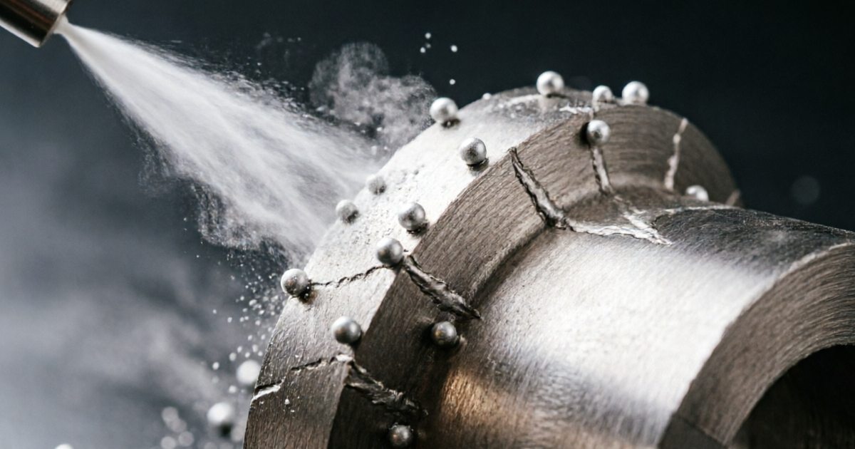
Bead embedment — ceramic particles lodged in the surface of a nylon SLS part — is one of the most consequential process failures in SLS depowdering. Embedded beads create surface contamination that interferes with dyeing (producing pinholes or uncoloured spots), coating adhesion (local delamination), and dimensional measurement (raised surface spots that appear as dimensional non-conformances).
Causes
- Excess blast pressure: energy above the material’s surface yield stress drives beads into the surface during impact rather than allowing clean rebound
- Degraded, angular media: beads that have broken down from spherical to angular have a higher tendency to embed due to their irregular impact geometry
- Reentrant features: acute internal corners, blind holes, and undercuts create accumulation zones where beads can pack and progressively embed under continued blast impact
- High-velocity pressure-feed at same PSI as suction-feed protocol: over-energy delivery leading to embedment on parts that were clean at suction-feed settings
Detection
Inspect suspected embedment areas at 5–10× magnification under oblique light. Embedded ceramic beads appear as white or cream-coloured spherical inclusions sitting above or flush with the nylon surface. Under UV light (365 nm), ZrO₂ beads may show weak fluorescence that distinguishes them from the nylon background.
Prevention
- Stay within the qualified pressure range; never increase pressure beyond specification without a formal re-qualification
- Monitor media condition by sieve analysis; maintain the size distribution within the specified range to preserve spherical morphology
- Reduce pressure on parts with acute internal angles or blind features
- Limit cycle time: once the semi-sintered skin is removed, additional blast time does not clean further — it only risks embedment and dimensional removal
Bead size must be specified before pressure — this article provides the complete size selection matrix for all SLS materials and geometry types.
7. Process Qualification and Parameter Documentation
A qualified blast protocol is a documented set of parameters — bead grade, bead size, pressure, nozzle, standoff, cycle time, and media charge state — that consistently delivers the specified surface quality (Ra, powder-free status) within the dimensional tolerance of the part. Qualification is performed once per part design and then maintained as the frozen production specification.
Minimum qualification record content
- Part number and revision
- Ceramic bead grade (ZS / ZrO₂ / alumina-silicate) and size range (mm)
- Blast cabinet type (suction-feed / pressure-feed)
- Inlet pressure at qualification (PSI), measured at nozzle inlet
- Nozzle diameter (mm) and standoff distance (mm)
- Cycle time (minutes)
- Media charge state at qualification (cycles since last replacement or top-up)
- Ra result on reference coupon (µm, surface orientation specified)
- Pre-blast and post-blast dimension on at least one OD and one ID reference feature
- Visual inspection result: powder-free Y/N, embedment absent Y/N
For SLS parts used in regulated applications (medical devices, aerospace), the blast process qualification should be maintained as a special process validation record (e.g., per NADCAP, AS9100, ISO 13485). Jiangsu Henglihong Technology Co., Ltd. can supply Certificate of Conformance and material data sheets for ceramic bead media to support customer process validation dossiers.
Questions fréquemment posées
In a suction-feed cabinet, compressed air creates a venturi that draws media from the reservoir at lower bead velocity for the same inlet PSI. In a pressure-feed system, the media pot is pressurised directly, propelling beads at higher velocity. For equivalent cleaning at the same inlet pressure, pressure-feed delivers approximately 30–50% more kinetic energy per impact. When converting a suction-feed protocol to pressure-feed, reduce inlet pressure by 10–15 PSI to match impact energy. For SLS nylon, suction-feed is the preferred starting configuration because its lower velocity provides a safer process window for thin-walled features and complex geometry.
Run the first blast cycle on a qualification part in 2-minute increments. After each increment, remove the part, blow clean, and inspect under directional light for completeness of powder removal on all surfaces and any signs of over-blasting on thin features. The minimum cycle time at which all inspection criteria pass is your baseline. Add 10% to this baseline for the production specification to accommodate normal media charge aging. Document all parameters (pressure, bead grade, size, nozzle, cycle time, media charge state) and the Ra result on a reference coupon at qualification. This becomes the frozen production specification.
Bead embedment occurs when ceramic beads become lodged in the nylon surface rather than bouncing off cleanly. It is caused by: blast pressure above the material surface yield stress; beads that have become irregular or angular due to degradation (maintain sieve-analysis monitoring); and reentrant features such as acute internal corners where beads can accumulate and pack. Prevent by staying within qualified pressure limits, maintaining the media charge within its specified size distribution, reducing pressure on parts with acute internal geometry, and avoiding extended blast cycles beyond the point of complete powder removal.
Modest pressure adjustment (3–5 PSI increase) can compensate for the gradual decline in per-impact energy as beads wear and average particle size decreases. However, sustained Ra drift upward despite pressure increases is a sign the media charge is approaching end of life and needs top-up or partial replacement — do not continue raising pressure as a long-term substitute for media management. The better approach is to include a 10% cycle time buffer at qualification (rather than pressure increase) and use sieve analysis monitoring to replace media before significant performance degradation occurs.
Related Articles in This Series
Return to the Ceramic Beads for SLS Powder Removal — Complete Guide for the full overview.
Bead size must be set before pressure — the complete selection matrix for all SLS materials.
Full Ra dataset — how pressure interacts with bead size to control surface roughness.
How pressure and cycle time control material removal from SLS parts.
Applying pressure and cycle time parameters to the most common SLS material.
Low-pressure protocol for flexible SLS — the most demanding pressure calibration challenge.
How media aging affects blast pressure performance and when to top up the charge.
Need Help Setting the Right Blast Pressure for Your SLS Operation?
Jiangsu Henglihong Technology Co., Ltd. supplies ceramic blasting beads with full technical documentation — including recommended pressure ranges by bead grade and size. Tell us your SLS material, part geometry, and blast cabinet type, and we will recommend starting parameters and supply samples for first-article qualification.
Request Technical SupportFiltres