How Plastic Media Is Used in Aerospace Depainting
Every commercial airliner is stripped to bare metal and completely repainted on a cycle of roughly five to seven years. Military aircraft are stripped and repainted on even tighter schedules — some tactical aircraft every two to three years depending on operational tempo and environmental exposure. Multiply that across a fleet of hundreds or thousands of airframes, and aerospace depainting becomes one of the largest-volume, most technically demanding surface preparation operations in any industry.
For most of the twentieth century, the method of choice was chemical stripping: applying highly caustic alkaline or solvent-based strippers to the aircraft skin, waiting hours for the coating to soften, and removing the result with high-pressure water blast. The process worked, but it generated enormous volumes of hazardous chemical waste, required extensive neutralization of the stripped surfaces, and was progressively falling out of regulatory favor as environmental controls tightened.
Plastic media blasting — the use of engineered polymer abrasive particles propelled by compressed air — emerged as the primary replacement for chemical stripping in aerospace depainting starting in the 1980s, driven by U.S. Air Force programs seeking to reduce solvent and hazardous waste generation in depot maintenance operations. Today, plastic media blasting is the dominant depaint method for military aircraft globally and is increasingly specified for commercial airline maintenance. This guide explains why, how the process works, and what the technical requirements are for qualified aerospace depainting operations.
For a foundational overview of plastic media types, see: What Is Plastic Media? The Complete Guide.
Why Aerospace Depainting Requires a Specialized Approach
Stripping paint from an aircraft is categorically different from stripping paint from an automobile or an industrial component. The governing constraints in aerospace depainting are not primarily about efficiency or convenience — they are about structural integrity, fatigue life, and airworthiness certification. Every decision about media type, blast parameters, and process sequence is made against the backdrop of a fundamental regulatory requirement: the aircraft must emerge from the depaint process in a condition that is aeronautically safe and certifiably airworthy.
Three structural realities define why aerospace depainting demands this level of rigor:
Aluminum alloy fatigue sensitivity. Aircraft aluminum alloys — particularly the 2000-series and 7000-series high-strength alloys used for primary structure — are fatigue-sensitive materials. Their fatigue life (the number of load cycles they can endure before initiating a crack) is directly affected by the state of their surface. Any surface treatment process that introduces tensile residual stress, removes material beyond a micro-scale profile, or creates surface discontinuities reduces fatigue life. A properly controlled plastic media blast process introduces no net tensile residual stress and removes no measurable aluminum — but an improperly controlled process can do both, with consequences that may not manifest until the aircraft has accumulated thousands of additional flight hours.
Dimensional criticality. Aircraft skins, particularly on wing panels and pressurized fuselage sections, are manufactured to tight thickness tolerances. Processes that remove metal — like aggressive mineral abrasive blasting — can thin skins below their minimum acceptable gauge over multiple depaint cycles. Plastic media blasting, because it fractures at the metal surface rather than cutting into it, does not remove measurable quantities of metal from aluminum substrates at qualified parameters.
Chromate primer exposure and management. Most legacy military aircraft and many older commercial aircraft carry chromate-containing primers — specifically MIL-PRF-23377 zinc chromate or barium chromate primers — as their primary corrosion protection layer. These primers are highly effective corrosion inhibitors but contain hexavalent chromium, a regulated carcinogen. The depaint process that removes these coatings generates chromate-contaminated blast media waste and dust, which must be managed under strict environmental and occupational health regulations.
The History: From Chemical Strip to Plastic Media
The shift from chemical stripping to plastic media blasting in aerospace maintenance is one of the clearest examples of environmental regulation driving process innovation in industrial manufacturing.
Through the 1970s, chemical stripping was the universal aerospace depaint method. The process involved applying methylene chloride-based paint strippers or high-pH alkaline strippers to the aircraft skin, typically using brushes or spray equipment inside a hangar. The stripper softened the coating layers, which were then removed with scrapers and high-pressure water. The resulting effluent — a mixture of water, caustic chemicals, dissolved paint, and chromate primer residue — was collected in floor drains and treated as industrial wastewater.
By the early 1980s, tightening environmental regulations around methylene chloride (a probable human carcinogen) and hexavalent chromium in wastewater were making chemical stripping increasingly costly and difficult to operate in compliance. The U.S. Air Force, which operates the largest fleet maintenance operation in the world, began funding research into alternative depaint technologies that could replace chemical stripping without compromising maintenance quality or aircraft structural integrity.
The result was the development and qualification of plastic media blasting under a series of Air Force programs culminating in the promulgation of MIL-P-85891A in 1989 — the military specification that defined the media types, test requirements, and process controls for plastic blast media in aircraft maintenance. By the mid-1990s, plastic media blasting had become the standard depaint method at Air Force and Navy depot maintenance facilities across the United States. The Marine Corps, Army, and allied military aviation organizations followed, and the technology progressively transferred into commercial airline heavy maintenance.
Today, plastic media blasting is used to depaint aircraft ranging from single-engine trainers to wide-body commercial transports, across military, commercial, and general aviation contexts, with the MIL-P-85891A standard as the common technical foundation across all sectors.
MIL-P-85891A: The Standard That Governs It All
MIL-P-85891A, Plastic Media, Abrasive Blasting, is the foundational document for aerospace plastic blast media. It was developed under the auspices of the U.S. Department of Defense to establish minimum performance requirements for plastic blast abrasives used in aircraft depaint and surface preparation operations. Understanding this standard is essential for anyone involved in aerospace depaint procurement, process engineering, or quality assurance.
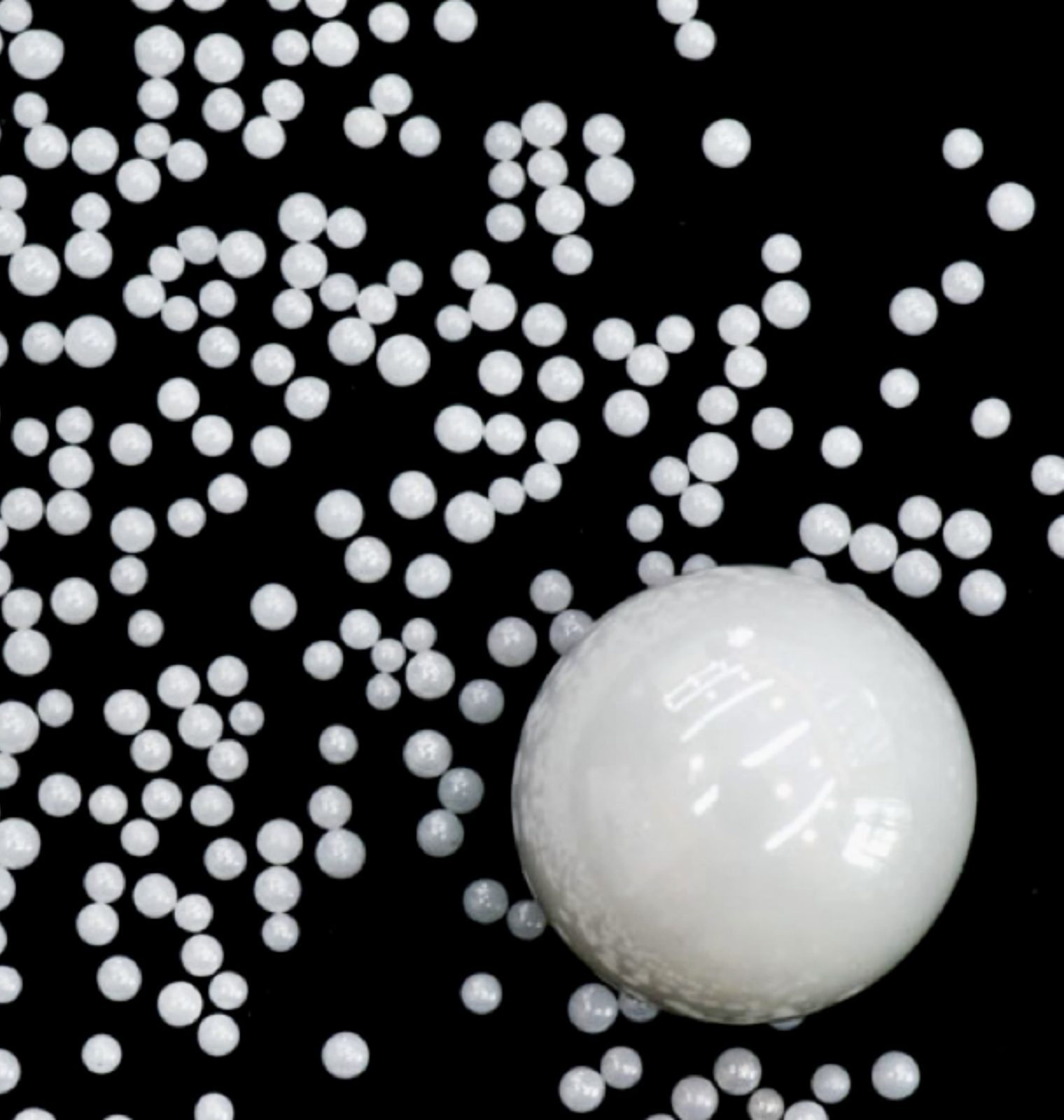
The standard defines five media types by resin chemistry:
| Type | Résine | Dureté Mohs | Primary Use in Aerospace | Availability |
|---|---|---|---|---|
| Type I | Polyester | ~2.5 | Tumbling/mass finishing; rarely blast | Limited suppliers |
| Type II | Urea Formaldehyde | ~3.5 | Primary aerospace depaint media; aluminum structures, standard MIL-SPEC coatings | Widely available; most common |
| Type III | Melamine Formaldehyde | ~4.0 | Steel structures, titanium; harder coatings; less common in aerospace | Available; less common |
| Type IV | Urea-Melamine Blend | ~3.7 | Intermediate applications; specialty use | Specialty suppliers only |
| Type V | Acrylic (PMMA) | ~3.0 | CFRP composites, radomes, sensitive structures; essential for composite-intensive aircraft | Available; higher cost |
For each type, MIL-P-85891A specifies minimum performance requirements including: particle size distribution (percentage passing and retained at each mesh screen), bulk density limits, moisture content (≤1.0% for Type II), pH range (7.0–9.0 for Type II), free formaldehyde content (≤0.1%), and hardness verification. Suppliers must provide a Certificate of Conformance (CoC) for each lot shipped, documenting lot-specific test results against each specification requirement.
Aerospace Coating Systems Being Removed
Understanding what is being removed is essential to selecting correct blast parameters. Military and commercial aircraft carry multi-layer coating systems whose individual layers differ significantly in hardness, adhesion, and resistance to abrasive removal:
The depaint objective is complete removal of layers 2–5 (all paint and primer layers) while leaving the conversion coating (layer 1) and substrate (layer 0) intact. This is the precise operational requirement that plastic media blasting is engineered to meet — and that chemical stripping, for all its drawbacks, achieves through a different mechanism (chemical dissolution rather than mechanical abrasion).
Aircraft Substrate Alloys & Media Compatibility
Modern military and commercial aircraft use a range of structural materials, each with different hardness characteristics and blast media requirements:
Zone-by-Zone: Different Areas, Different Requirements
An aircraft is not a uniform structure. Different zones have different substrate materials, coating systems, access constraints, and structural criticality — each of which affects the appropriate blast media and process parameters. Here is how a typical military aircraft breaks down by depaint zone:
Military Aircraft Depainting
- Primary driver: Corrosion control and inspection access — stripping exposes all substrate surfaces for Non-Destructive Inspection (NDI)
- Depaint interval: 2–5 years depending on platform, operational environment, and inspection requirements
- Governing documents: Aircraft-specific Technical Orders (TO), weapon system maintenance manuals, depot process specifications
- Media specification: MIL-P-85891A mandatory; Certificate of Conformance required per lot
- Process control: Written process specification required; operator qualification and recurring training
- Chromate management: Full OSHA and EPA compliance required; medical surveillance for operators
- Post-strip inspection: NDI (eddy current, penetrant, ultrasonic) before repaint; fatigue life assessment for primary structure
- Examples: F-16, F/A-18, C-130, B-52, CH-47, UH-60, P-8
- Primary driver: Livery repaint and corrosion inspection — airlines repaint on rebranding, lease return, and heavy maintenance cycles
- Depaint interval: 5–8 years, typically aligned with D-check (heavy maintenance visit)
- Governing documents: Aircraft Maintenance Manual (AMM), OEM service bulletins, EASA/FAA-approved maintenance procedures
- Media specification: MIL-P-85891A or OEM-specified equivalent; airlines and MRO facilities specify in their Process Specifications (PS)
- Process control: Part 145 repair station requirements; approved data required for any process affecting airworthiness
- Composites: B787 (extensive CFRP fuselage), A350 require Type V acrylic for composite zones — growing requirement as composite-intensive aircraft age
- Examples: B737, B757, B767, B787, A320, A330, A350, A380
The military and commercial sectors share the same underlying plastic media technology but differ significantly in their regulatory frameworks, documentation requirements, and technical authority structures. Military depaint processes are controlled through Technical Orders (TOs) approved by the respective service’s engineering authority. Commercial processes are controlled through OEM-approved Aircraft Maintenance Manual procedures and Part 145 repair station process specifications, with FAA or EASA oversight.
Commercial Airline Heavy Maintenance
For commercial airlines, the full-aircraft depaint and repaint cycle is typically integrated into the D-check (also called 12-year check or heavy maintenance visit depending on operator and OEM terminology), which is the most comprehensive scheduled maintenance event in an aircraft’s life cycle. The aircraft is completely stripped of all interior components, systems are opened for inspection, and the exterior is fully deprimed and repainted.
The commercial depaint context differs from military in several important ways that affect how plastic media blasting is applied:
Livery Economics
For commercial operators, depaint and repaint is not just a maintenance event — it is a significant brand and appearance investment. Airlines typically spend $150,000–$400,000 per aircraft on a full repaint, depending on aircraft size and livery complexity. This investment creates a strong incentive to deliver bare metal surfaces that are uniformly clean, dimensionally unchanged, and immediately ready for primer application — which is precisely what a well-controlled plastic media blast process provides. Any depaint method that introduces new defects (warped panels, thinned areas, residual contamination) adds body work and repair costs that erode the economics of the repaint investment.
OEM Involvement
Major commercial aircraft OEMs — Boeing, Airbus, Embraer, Bombardier — have each issued maintenance documentation covering plastic media blasting parameters for their specific aircraft. These documents are incorporated into the Aircraft Maintenance Manual (AMM) and constitute the approved technical basis for depaint operations at Part 145 repair stations. Any deviation from AMM-specified parameters requires an Engineering Order (EO) or equivalent approved-data document. MRO facilities performing commercial depaint work must hold appropriate approvals and operate within AMM parameters — using a process that has not been validated against the specific aircraft type is not acceptable under Part 145 repair station quality systems.
Composite-Intensive Modern Aircraft
The Boeing 787 and Airbus A350 represent a step change in commercial aircraft construction — both use CFRP for approximately 50% of their primary structure by weight, including large sections of the fuselage barrel. These aircraft require fundamentally different depaint strategies from aluminum-dominated legacy types, with Type V acrylic media used across all composite zones and carefully managed transition protocols at the interfaces between composite fuselage sections and aluminum structural elements. As these aircraft age into their first D-check cycles (2025 onward for the earliest 787s), the commercial MRO industry is building the process experience and facility infrastructure to handle composite-intensive aircraft at scale.
Composite Structure Depainting
The depainting of composite aircraft structures — CFRP panels, fiberglass fairings, Nomex-core sandwich structures — represents the most technically demanding application of plastic blast media in aerospace maintenance, and the one where process qualification rigor matters most. The substrate damage mechanisms, qualification requirements, and post-blast inspection methods for composite depainting are distinct from those for metallic structures.
The two primary damage modes for CFRP under blast operations are fiber severance (individual carbon fibers cut by abrasive particle impact) and interlaminar delamination (separation of plies driven by blast shockwave energy). Both forms of damage reduce structural performance in ways that cannot be detected by visual inspection — a CFRP panel can appear undamaged externally while carrying significant internal delamination. This is why composite depaint process qualification requires ultrasonic C-scan inspection before and after the qualification blast sequence, not just visual inspection.
Type V acrylic media is required for all bare CFRP depaint operations. The combination of PMMA’s thermoplastic deformation behavior and lower particle density reduces peak substrate stress to the level where coating removal can be achieved without initiating fiber or matrix damage within the qualified process window. Type II urea can be used on CFRP at very low pressures (15–25 PSI) per some process approvals, but the process window is significantly narrower and the risk of operator variation-induced damage is substantially higher.
For composite depainting process qualification, the minimum accepted test sequence typically includes:
- Baseline C-scan and visual inspection of representative composite coupons
- Blast sequence at proposed parameters (typically 3–5 full coating removal passes)
- Post-blast C-scan comparison to detect any delamination not present in baseline
- Microscopic cross-section examination of blasted surface at 40–100× to check fiber condition
- Mechanical testing (if structurally critical application): open-hole tension or compression after blast vs. unblasted baseline
- Environmental testing: temperature cycling and humidity soak of blasted coupons to detect latent delamination propagation in service conditions
Full guidance: Acrylic (Type V) Plastic Media for Sensitive Surfaces.
Qualified Blast Parameters
These parameter ranges represent the consensus of established aerospace depaint process specifications for the most common aircraft structural materials. They are starting points for process qualification, not substitutes for aircraft-specific maintenance manual requirements:
The Qualified Depaint Process: Step by Step
Work Order and Documentation Setup
Before any blast work begins, establish the formal work order referencing the applicable Technical Order (military) or AMM procedure number (commercial). Verify that the operator performing the work is qualified per the applicable process specification — aerospace depaint operators typically require documented initial training and recurring annual qualification on the specific process and aircraft type. Record media lot number and Certificate of Conformance data in the work order.
Aircraft Preparation and Protection
Position aircraft in the blast hangar on approved jacks or ground support. Close all fuel and oil filler caps. Install blanking plates on all engine inlets, exhaust nozzles, environmental control system ports, and pitot-static system probes. Mask all windows (cockpit and cabin) with rigid backing panels — never rely on masking tape and paper alone for glass protection. Remove or mask all rubber seals, antenna waveguides, and composite components that require different media parameters than the main fuselage skin. Remove landing gear, flight control hinges, and other movable components that would shadow blast zones or trap media.
Most aircraft maintenance manuals include a specific masking diagram as an approved data reference — use it, do not improvise.
Equipment Calibration and Media Verification
Verify nozzle pressure at the nozzle inlet with an inline gauge — not at the compressor regulator. Set pressure to the lower end of the applicable range for the zone being worked. Inspect nozzle for wear; replace if bore is more than 1/16-inch oversize. Verify media type and mesh size match the zone specification. Check media moisture by observing flow — clumping or erratic nozzle output indicates moisture contamination requiring media replacement. Run the reclaim system through one dry cycle to verify air wash separator and screen deck are functioning correctly before loading production parts.
Trial Blast on Qualification Area
Before proceeding to flight-critical structure, perform a trial blast on a non-critical area of the same substrate material (inner fuselage skin panel in a wheel well, for example) at the target parameters. Inspect the trial area for complete coating removal and measure surface profile with Testex Press-O-Film replica tape. If profile exceeds the maximum specified in the maintenance manual (typically 0.5–1.0 mil for aluminum), reduce pressure or increase mesh fineness before proceeding to primary structure. Document trial area location and measurements in the work order.
Systematic Blast Sequence
Work the aircraft in defined zones — typically starting at the fuselage nose and working aft, then upper wing surfaces, lower wing, vertical and horizontal stabilizers, and finally nacelles and pylons. Within each zone, blast in overlapping passes with consistent nozzle travel speed. Transition to composite-specific parameters (Type V Acrylic, lower pressure) when moving from metallic to composite zones — never use metallic parameters on composite surfaces. Document zone completion as each area is cleared.
At rivet lines, lap joints, and skin doublers, pay particular attention to complete coating removal in the recessed areas at joint edges. These are common locations where primer residue remains after the main skin is stripped, creating adhesion discontinuities in the subsequent repaint.
Post-Blast Inspection
After blasting is complete, blow off all media dust with clean dry compressed air using a fan nozzle to avoid concentrated pressure on bare skin. Perform a complete visual inspection of the bare substrate under adequate lighting (minimum 50 foot-candles at the inspection surface). Use UV light to detect any residual fluorescent primer (if the aircraft was painted with a fluorescent-penetrant-compatible primer). Inspect all fastener holes for media entrapment. Inspect the conversion coating condition — chromate conversion coating should appear as a uniform golden-tan color; local discoloration may indicate areas that received insufficient blast energy or areas where the conversion coat was disturbed.
On high-cycle aircraft, the post-blast inspection window is also when Non-Destructive Inspection (eddy current, fluorescent penetrant, ultrasonic) of fatigue-critical structure is performed before re-prime — coordinate NDI scheduling before stripping so NDI personnel can access the bare structure immediately after blast.
Surface Treatment and Prime Window Management
Bare aluminum begins oxidizing immediately after blasting. The maximum allowable time between bare metal exposure and primer application is specified in the applicable maintenance document — commonly 4 hours in controlled hangar conditions (below 75°F / 24°C and below 60% RH), and as short as 2 hours in humid or warm conditions. Apply corrosion-inhibiting compound (CIC) or touch-up conversion coating to any areas where the original chromate conversion coating has been disturbed. Apply primer (typically MIL-PRF-23377 chromate or approved non-chromate equivalent) within the specified window. Document primer lot number and application time in the work order.
Plastic Media vs Chemical Stripping: Full Comparison
- Environmental: No liquid chemical waste stream; dry process. Solid waste (media + paint) is manageable under solid waste regulations (unless chromate-contaminated)
- Operator safety: Physical blast hazard (PPE required) but no chemical exposure from the stripping agent itself; primary chemical hazard is from stripped coating residue
- Strip time: 4–12 hours for a typical fighter aircraft; 12–24 hours for a large transport
- Surface profile: Controlled 0.5–1.0 mil profile produced — ready for primer without additional surface conditioning
- Substrate effect: No metal removal; no hydrogen embrittlement risk; no seam penetration
- Composite compatibility: Excellent (Type V Acrylic); only practical dry stripping method for CFRP
- Cost per aircraft: Generally lower than chemical, especially when waste disposal costs are included
- Limites : Cannot reach inside sealed structure; line-of-sight only; requires blast hangar infrastructure
- Environmental: Large volume liquid hazardous waste; complex wastewater treatment required; methylene chloride (MCL) restricted by EPA Significant New Use Rule
- Operator safety: Skin, eye, and respiratory exposure risk to caustic strippers and dissolved chromate primer; full chemical PPE required throughout process
- Strip time: 8–48 hours depending on dwell time requirements; significant process variability
- Surface profile: Chemical dissolution leaves near-zero profile; conversion coat may be attacked; requires phosphoric acid etch or re-conversion before prime in many processes
- Substrate effect: Risk of hydrogen embrittlement on high-strength aluminum from acidic strippers; seam penetration may damage seam sealant and spot weld adhesive
- Composite compatibility: Chemical strippers attack CFRP resin systems; generally incompatible with CFRP composites
- Cost per aircraft: High chemical and waste disposal costs; falling out of use for economic and regulatory reasons
- Avantages : Reaches inside sealed cavities; can remove coatings in areas inaccessible to blast nozzle
Fatigue Life Considerations
The relationship between plastic media blasting and aircraft structural fatigue life is one of the most extensively studied technical questions in the history of this process, and the answer is nuanced enough to deserve a dedicated section.
The Research Baseline
Multiple studies conducted by the U.S. Air Force, the National Aeronautics and Space Administration, and independent research institutions in the 1980s and 1990s examined the effect of plastic media blasting on the fatigue life of aluminum alloy specimens representative of aircraft primary structure. The consistent finding was that plastic media blasting at parameters within the MIL-P-85891A-compliant process window does not produce a statistically significant reduction in fatigue life compared to pre-blast baseline specimens. Some studies found a slight fatigue life improvement, attributed to beneficial compressive residual stress introduced by the blast peening effect at the surface.
The Critical Caveat: Process Window Exceedance
The research finding above is bounded by the condition “within the qualified process window.” Blasting that exceeds the qualified parameter envelope — specifically, pressure above the specified maximum, mesh coarser than specified, or standoff closer than the minimum — can produce tensile residual stress at the surface rather than compressive, which does reduce fatigue life. The mechanism is straightforward: at excessive blast energy, the plastic deformation of the surface layer puts it in tension relative to the substrate below, creating a condition analogous to a tensile pre-load on the fatigue crack initiation region.
This is why process control in aerospace depaint is not a bureaucratic preference — it is a structural engineering requirement. The parameters specified in the Technical Order or AMM are not conservative guidelines with room for operator judgment. They are the boundary conditions within which the structural safety of the aircraft is preserved. Nozzle pressure above the specified maximum, even for a brief period, puts the aircraft’s structural safety guarantee at risk in a way that cannot subsequently be detected by inspection.
Practical Implications
For organizations performing aerospace depaint operations, the fatigue life consideration drives three specific practices:
- Inline nozzle pressure gauging: Pressure must be measured at the nozzle, not inferred from the compressor setting. Hose pressure drop is real and variable; assuming nozzle pressure equals compressor pressure is an engineering error.
- Nozzle wear monitoring: Nozzle bore growth increases flow at a given compressor pressure, which raises nozzle velocity and effective blast energy. A worn nozzle operating at the “correct” compressor setting may be producing above-limit blast energy at the part surface.
- Documentation: Every blast operation on primary structure should be documented with actual measured nozzle pressure, media type and lot, mesh size, and zone worked. This documentation becomes part of the aircraft’s maintenance history and the structural engineering traceability record.
Documentation & Traceability Requirements
Aerospace depaint operations generate a documentation burden that is significantly higher than automotive or industrial blast work. This is not administrative overhead — it is the engineering traceability system that allows the aircraft’s maintenance history to be reconstructed and verified at any point in its service life.
Media Certificate of Conformance
Lot-specific CoC documenting test results against every MIL-P-85891A parameter. Must reference media type, mesh size, lot number, manufacturer, and test dates. Retained in depot quality records for the life of the aircraft program.
Operator Qualification Record
Documentation that the blast operator is trained and currently qualified per the applicable process specification. Typically requires initial training, supervised practice on qualification coupons, and annual recertification. Must be traceable to the specific aircraft maintenance record.
Equipment Calibration Records
Calibration status of pressure gauges (inline nozzle gauges must be calibrated on a defined interval — typically annually). Nozzle wear measurements recorded at defined intervals. Air wash separator calibration records. Dust collector performance records.
Trial Blast Records
Documentation of trial blast location, parameters used, surface profile measurement result, and inspector signature. Required before beginning work on flight-critical structure on each aircraft. Cannot be carried over from a previous aircraft even of the same type.
Zone Completion Checklist
Sequential sign-off of each blast zone as it is completed and inspected. Records actual parameters used (not just intended parameters), inspector identification, date, and time. Provides the structural engineering traceability that documents which zones were blasted at what energy level.
Environmental Conditions Log
Temperature and relative humidity at time of blast and at time of primer application. Both must be within the ranges specified in the maintenance manual. Documented by the operator at the beginning of each work shift and whenever environmental conditions change.
NDI Inspection Records
Results of Non-Destructive Inspection performed on bare structure after depaint — eddy current, fluorescent penetrant, or ultrasonic depending on the inspection requirement. NDI findings and dispositions become part of the aircraft’s permanent structural maintenance record.
Waste Characterization & Disposal Records
TCLP or other appropriate characterization of spent blast media mixed with stripped paint residue. Disposal manifest (EPA Uniform Hazardous Waste Manifest for hazardous waste). Retained for minimum 3 years per RCRA requirements; longer if state regulations require.
Waste Management & Environmental Compliance
Aerospace depaint waste management is one of the most complex environmental compliance challenges in aviation maintenance, driven by the presence of hexavalent chromium in stripped primer residue and the volume of waste generated in large-scale depot operations.
Waste Stream Characterization
Spent plastic blast media from aircraft depaint operations is a mixture of fractured media particles, stripped paint fragments, and primer residue. The hazardous waste classification of this mixture depends entirely on its chemical composition:
- Chromate primer residue (Cr⁶⁺): If the stripped coatings include MIL-PRF-23377 chromate primer, the waste must be tested by TCLP (Toxicity Characteristic Leaching Procedure) for chromium. If TCLP chromium concentration exceeds 5.0 mg/L, the waste is classified as D007 Hazardous Waste under RCRA and must be managed accordingly — licensed transporter, licensed treatment/disposal facility, EPA Uniform Hazardous Waste Manifest for each shipment.
- Non-chromate primer residue: Aircraft stripped of non-chromate primer systems only (newer coatings, or aircraft that have previously transitioned to non-chromate) produce waste that may be non-hazardous. Confirm with TCLP testing before assuming non-hazardous classification.
- Lead-containing primers: Some older aircraft carry lead-containing surfacers or primers. If lead is present, D008 (lead) hazardous waste classification also applies.
Air Emissions
Blast hangar ventilation systems must be designed to capture and filter blast dust to protect both operators and the surrounding environment. HEPA filtration or equivalent is typically required for hangar exhaust air when blasting chromate-coated aircraft. The concentration of hexavalent chromium in exhaust air must be maintained below the OSHA Permissible Exposure Limit (PEL) of 5 µg/m³ as an 8-hour TWA for areas where operators are present, and below ambient air emission limits for the facility operating permit.
Pollution Prevention Hierarchy
The most cost-effective environmental strategy for aerospace depaint operations is chromate primer elimination at the source — transitioning aircraft paint systems to non-chromate primer equivalents. The U.S. Air Force and Navy have both ongoing programs to qualify and implement non-chromate primer systems across their fleets, which will progressively reduce the regulatory burden of waste management as aircraft cycle through repaints using the new systems. Until that transition is complete, rigorous waste management protocols remain mandatory for any facility performing depaint on chromate-coated aircraft.
Questions fréquemment posées
How many times can an aircraft be depainted with plastic media before cumulative effects become a concern?
The research consensus, based on multiple Air Force-funded studies, is that repeated plastic media blast cycles at qualified parameters do not produce cumulative fatigue life degradation — each blast cycle produces the same near-neutral residual stress state as the first, rather than incrementally worsening the surface condition. This finding is what makes plastic media blasting sustainable as a recurring maintenance process over the full service life of an aircraft. However, the conclusion depends entirely on maintaining parameters within the qualified process window on every cycle. An aircraft that has been over-blasted on even one cycle has an altered residual stress state that may not be visible on subsequent inspection but affects fatigue life accumulation. The practical answer is: there is no defined limit on the number of plastic media depaint cycles for aircraft maintained to process specification, but the process must be correctly executed on every cycle without exception.
Does plastic media blasting remove the chromate conversion coating (Alodine) from aluminum?
Plastic media blasting does partially disturb or remove chromate conversion coating from aluminum surfaces. Conversion coating (Alodine/Iridite per MIL-DTL-81706) is a very thin (0.01–0.05 mil) chemically bonded layer — it is not a free-standing film and does not delaminate the way paint does. However, the mechanical action of blast media does modify the conversion coating surface, reducing its visual intensity and potentially removing it in local areas. For this reason, aerospace maintenance procedures typically require touch-up application of conversion coating to any areas where the original coating has been disturbed before re-prime application. The conversion coating replenishment step is critical to the long-term corrosion protection of the repainted structure — omitting it leaves bare aluminum with only the organic primer as its corrosion barrier, significantly reducing corrosion performance compared to conversion coat + primer systems.
Can plastic media blasting be performed on an aircraft that has not been fully disassembled?
Yes — most depot depaint operations are performed on aircraft that are largely assembled, with engines removed and systems powered down, but with structural assemblies (wings, stabilizers, fuselage) intact. The key requirements for blasting an assembled aircraft are comprehensive masking of all openings, sensors, and protected components per the applicable Technical Order masking diagram; complete engine inlet and exhaust blanking; removal of all flight surfaces that carry composite materials requiring different blast parameters; and post-blast inspection for media entrapment in any crevice, fastener hole, or system interface that could trap media. Media entrapment is particularly critical — trapped media in structural crevices or hydraulic fitting areas can cause corrosion damage significantly worse than the original stripped coating. A formal media entrapment inspection, using bright lighting and compressed air flushing of all potential entrapment locations, must be completed and documented before the aircraft returns to service.
What is the minimum facility infrastructure needed to perform qualified aerospace depaint operations?
A minimum-capability aerospace depaint facility requires: an enclosed blast hangar of sufficient size to accommodate the largest aircraft to be worked (typically minimum 100 ft × 100 ft × 30 ft clear height for fighter/attack aircraft; larger for transports); ventilation and dust collection rated for the hazardous materials in the waste stream; a media reclaim system (floor recovery, air wash separator, screen classification) sized for the expected media throughput; a compressor system capable of sustained delivery at nozzle pressure (typically 25–100 HP rotary screw compressor); temperature and humidity control (or monitoring with work stoppage limits); HEPA filtration on exhaust air when blasting chromate-coated aircraft; hazardous waste accumulation area for spent media; and a quality system that supports the documentation requirements described above. For NADCAP-accredited facilities (required for Tier 1 aerospace contractors and many DoD depot operations), additional audit requirements apply to process documentation, operator qualification, and calibration systems.
Is plastic media blasting approved for use on the Boeing 787 and Airbus A350?
Plastic media blasting is approved for use on both the 787 and A350, but with zone-specific media type requirements that reflect the composite-intensive construction of these aircraft. For metallic zones (aluminum frame elements, titanium fittings, certain door surrounds), standard Type II urea parameters apply per the respective Aircraft Maintenance Manual. For CFRP composite zones — which constitute approximately 50% of the structural surface on both types — Type V acrylic media is required, typically at Mesh 30–50 and pressures in the 20–35 PSI range. The 787 and A350 AMMs include specific depaint procedures and parameter tables for each structural zone. MRO facilities performing depaint work on these types must have their processes approved against the OEM-specified parameters and must use media that meets the specified requirements. The specific AMM section references should be obtained directly from Boeing or Airbus Customer Services — as living documents, AMMs are subject to revision, and the latest approved revision must be used.
Filtres