Improving Ra and Rz on 3D Printed Parts: How Abrasive Blasting Reduces Surface Roughness
Surface roughness — quantified as Ra (arithmetic mean roughness) or Rz (mean peak-to-valley height) — is the primary measurable output of abrasive blasting in AM post-processing. Every production metal AM facility and most advanced polymer AM operations specify and measure surface roughness on finished parts. Abrasive blasting is the most effective single-step method for reducing as-built AM surface roughness by 60–80%, creating a uniform, controlled surface texture that meets functional specifications for fatigue resistance, corrosion protection, coating adhesion, and dimensional compliance. This guide explains how blasting reduces Ra and Rz, what values are achievable for each AM process and alloy, how to use cascade blasting for finer results, and when to add secondary finishing processes for specifications below Ra 0.8 µm.
1. Understanding Ra and Rz in Additive Manufacturing
Surface roughness is a statistical description of the micro-geometry of a surface. For AM parts, two parameters dominate engineering specifications:
Ra — Arithmetic Mean Roughness
Ra is calculated as the arithmetic mean of the absolute deviation of the surface profile from its mean line over the evaluation length (typically 5 × λc, where λc is the cutoff wavelength). It is the most widely used single parameter for surface quality specification. Ra captures the average surface texture intensity but does not distinguish between peaked surfaces (many small sharp peaks) and pitted surfaces (few deep valleys) — two surfaces with the same Ra can have very different functional properties.
Rz — Mean Roughness Depth
Rz is the average height of the five deepest profile peaks and valleys within the evaluation length. For the same surface, Rz is always greater than Ra. For blasted AM surfaces, the typical relationship is Rz ≈ 4–7 × Ra. Rz is more sensitive to extreme features (deep valleys, high peaks) and is therefore more relevant to fatigue crack initiation (cracks start at valleys) and coating thickness adequacy (the coating must fill valleys without bridging gaps).
Sa and Sz — Areal Parameters
Sa (areal arithmetic mean height) and Sz (maximum height of the evaluation area) are the three-dimensional equivalents of Ra and Rz, measured per ISO 25178 using optical or confocal profilometry. Because AM surfaces are anisotropic — Ra measured parallel to layer lines differs from Ra measured perpendicular to them — areal parameters provide a more complete and representative characterisation of blasted AM surfaces. For high-accuracy surface specification on AM parts, Sa and Sz are preferred over Ra and Rz alone.
For all AM post-processing reporting in this guide, Ra is used as the primary metric (the most common specification parameter in industry), with Rz noted where it provides additional insight.
2. As-Built Ra/Rz Values by AM Process and Orientation
As-built surface roughness in AM is not uniform — it varies significantly with build orientation, process parameters, and alloy. Understanding the starting Ra is essential for selecting the correct blast parameters and setting realistic expectations for post-blast Ra.
| AM Process | Material | Up-skin Ra (µm) | Side-wall Ra (µm) | Down-skin Ra (µm) | Rz (approx.) |
|---|---|---|---|---|---|
| FDM (0.2mm layers) | ABS, Nylon | 5–12 | 15–25 | 18–30 | 5–8 × Ra |
| SLS | PA12 nylon | 10–16 | 12–20 | 14–22 | 4–7 × Ra |
| MJF | PA12 nylon | 8–12 | 8–15 | 10–18 | 4–6 × Ra |
| SLM/DMLS | Ti-6Al-4V | 8–14 | 10–18 | 18–30 | 4–7 × Ra |
| SLM/DMLS | 316L SS | 8–14 | 10–18 | 18–30 | 4–7 × Ra |
| SLM/DMLS | AlSi10Mg | 8–16 | 10–20 | 18–35 | 4–7 × Ra |
| SLM/DMLS | Inconel 718 | 8–15 | 12–20 | 20–35 | 5–7 × Ra |
| EBM | Ti-6Al-4V | 20–30 | 25–35 | 30–40 | 5–8 × Ra |
The data above illustrates two critical points: (1) down-skin surfaces are substantially rougher than up-skin surfaces for the same part; (2) EBM titanium starts roughly twice as rough as SLM titanium. Blast protocols must account for these starting Ra differences — a single parameter set will not achieve uniform final Ra across all orientations of a complex part without targeted attention to down-skin surfaces.
3. How Abrasive Blasting Reduces Surface Roughness
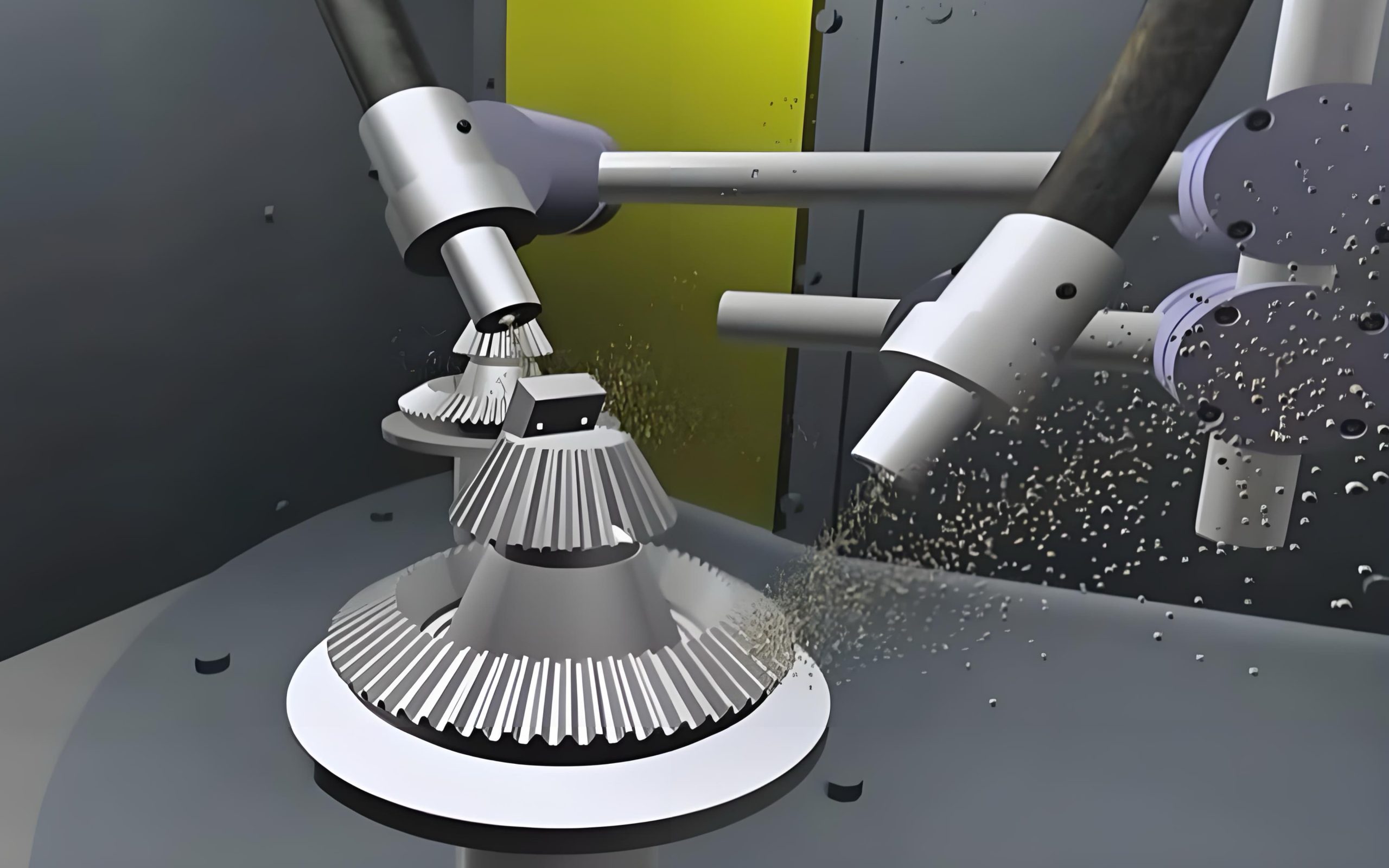
The Ra reduction mechanism of abrasive blasting depends on the media morphology:
Spherical Media (Glass Beads, Steel Shot, Zirconia): Peening Mode
Spherical particles impact the surface and plastically deform the material at the contact point. The high local contact stress flattens the surface peaks — the highest points on the Ra profile — by cold-working them. The peak material flows laterally into adjacent valleys, partially filling them. The net effect is a reduction in both peak height and valley depth, lowering Ra. This peening mechanism does not remove material in the traditional sense; it redistributes it. After multiple passes, diminishing returns set in as the remaining peaks are progressively smaller and require more energy per unit Ra reduction.
Angular Media (Al₂O₃, Steel Grit): Cutting Mode
Angular particles with sharp edges remove material by micro-cutting. Each impact of a sharp particle removes a tiny chip of surface material from the peak it strikes, leaving a sharp-edged micro-pit. The Ra reduction comes from peak removal, but the remaining micro-pits left by angular impacts create a characteristic surface texture that is rougher on a micro-scale than a peened surface. This is why angular media (Al₂O₃) at equivalent grit size produces a slightly higher Ra than spherical media (glass beads) at equivalent mesh size, despite both reducing Ra from the as-built condition.
Impact of Media Size on Ra
Media size directly determines the scale of surface modification. Coarse media (large particles, low mesh number) creates larger impact zones and removes larger peaks more rapidly, but leaves a coarser surface texture at the micro-scale. Fine media (small particles, high mesh number) creates smaller impact zones, producing a finer micro-texture but requiring longer cycle times. For the lowest achievable Ra in a single-stage blast, use the finest media that achieves adequate coverage in a reasonable cycle time.
4. Ra Achievable by Media Type and AM Material
| AM Material/Process | As-Built Ra (µm) | After Glass Beads 100–150M | After Glass Beads 150–200M | After Al₂O₃ 80–120 | After Al₂O₃ 150–220 |
|---|---|---|---|---|---|
| FDM ABS (vertical) | 15–25 | 4–8 | 3–6 | N/A | N/A |
| SLS PA12 nylon | 12–20 | 3–6 | 2–4 | N/A | N/A |
| MJF PA12 nylon | 8–15 | 2–4 | 1.5–3 | N/A | N/A |
| SLM Ti-6Al-4V (side) | 10–18 | 1.5–4 | 1–3 | — | — |
| SLM 316L SS (side) | 10–18 | 1.5–4 | 1–3.5 | 2–5 | 1.5–4 |
| SLM AlSi10Mg (side) | 10–20 | 1.5–4 | 1–3.5 | 2–5 | 1.5–4 |
| SLM Inconel 718 (side) | 12–20 | 1.5–4 | 1–3.5 | 2–5 | 1.5–4 |
| EBM Ti-6Al-4V (side) | 25–35 | 3–7 | 2–5 | — | — |
| SLM Ti-6Al-4V (down-skin) | 18–30 | 3–7 | 2–5 | — | — |
Note: Al₂O₃ is not used on titanium or stainless steel due to iron-free media requirements. All values are approximate ranges under optimised parameters; actual results depend on specific machine, powder, parameters, and part geometry.
5. The Cascade Blasting Technique
Cascade blasting is the sequential use of two or more blast stages with progressively finer media — starting with a coarser media to rapidly reduce as-built Ra, then following with a finer media to refine the surface to the target Ra. It is the most efficient approach when the as-built Ra is very high (EBM parts, FDM vertical surfaces, SLM down-skin surfaces) and the target Ra is low.
Example cascade for EBM Ti-6Al-4V (as-built Ra 25–35 µm, target Ra ≤ 3 µm):
- Stage 1: Glass beads 80–100 mesh at 70–80 psi — rapid peak removal; reduces Ra from 25–35 µm to 5–10 µm in 3–5 minutes
- Stage 2: Glass beads 150–200 mesh at 60–70 psi — surface refinement; reduces Ra from 5–10 µm to 1.5–4 µm in 3–5 minutes
Total cascade time: 6–10 minutes per part, achieving Ra below 4 µm. Compare to using only 150–200 mesh glass beads from the start on the same part: 10–15 minutes to achieve Ra 4–6 µm, without reliably reaching below 4 µm within reasonable cycle time.
The cascade principle also applies to Al₂O₃ blasting for pre-coating preparation:
- Stage 1: Al₂O₃ 80 mesh at 65–80 psi — aggressive peak removal, cleaning, and oxide removal
- Stage 2: Al₂O₃ 150–180 mesh at 55–65 psi — refine anchor profile to target Ra 2–4 µm for paint/powder coat
6. Media Sequence and Diminishing Returns
Understanding the diminishing returns of repeated blasting at the same parameters prevents over-processing and media waste:
- First pass: Largest Ra reduction — 50–70% of the total achievable reduction from blasting occurs in the first pass. The as-built peaks (tallest features) are addressed most rapidly.
- Second pass: An additional 15–25% Ra reduction is typical. Remaining smaller peaks are flattened.
- Third pass: 5–10% additional Ra reduction. Diminishing returns are pronounced.
- Fourth pass and beyond: Less than 5% additional Ra reduction; risk of increasing Ra by creating a more irregular micro-texture; unnecessary media and equipment wear.
Practical rule: define blast cycle time and number of passes by Ra measurement on first-article coupons, not by guesswork. Once the first-article Ra target is confirmed at a specific number of passes and parameters, use that as the production specification.
7. When Blasting Is Not Enough: Ra Below 0.8 µm
For applications requiring Ra below 0.8 µm — precision sealing surfaces, optical components, PVD coating substrates, certain medical devices — abrasive blasting must be followed by a secondary finishing process. The blasted surface at Ra 1–3 µm serves as the starting point for these secondary processes:
| Secondary Process | Starting Ra (after blast) | Achievable Ra | Compatible Materials | Notes |
|---|---|---|---|---|
| Electropolishing | 1–4 µm | 0.1–0.5 µm | Stainless steel, titanium, Al | Also passivates; changes dimensions |
| Vibratory superfinishing | 1–4 µm | 0.1–0.4 µm | Metals | Isotropic; no complex geometry |
| Manual polishing | 1–4 µm | 0.05–0.4 µm | All | Labour-intensive; directional |
| Laser polishing | 1–4 µm | 0.1–0.3 µm | Metals | High capital; line-of-sight only |
| Chemical smoothing | 1–4 µm | 0.1–0.4 µm | Some polymers | Hazardous chemicals; limited materials |
The blasted surface at Ra 1–3 µm requires significantly less secondary processing than the as-built AM surface (Ra 8–35 µm) to reach the same final Ra. Using blasting as a mandatory pre-step before secondary finishing is the most efficient workflow for tight Ra specifications.
8. Surface Roughness Measurement Standards for AM Parts
Accurate Ra measurement requires correct selection of measurement parameters, particularly the cutoff wavelength (λc) and the evaluation length. For blasted AM surfaces:
- ISO 4287 (profile) / ISO 4288 (measurement conditions): The primary standards for Ra and Rz measurement using contact profilometry. For blasted AM surfaces with Ra 1–10 µm, λc = 0.8 mm is the standard cutoff wavelength.
- Evaluation length: 5 × λc = 4.0 mm (five sampling lengths). For small AM part features where 4 mm measurement length is not available, document the reduced evaluation length and note this on the inspection record.
- Measurement direction: AM surfaces are anisotropic — Ra measured parallel to build layers differs from Ra measured perpendicular to build layers. Measure in the most critical direction for your application, or measure in both directions and report both values for a complete characterisation.
- ISO 25178 (areal): For R&D and critical applications, areal measurement using focus variation, confocal, or white light interferometry provides Sa, Sz, Sku, and Ssk — a complete three-dimensional surface characterisation that is more appropriate for the complex, isotropic blasted AM surface than a single-profile Ra measurement.
- Instrument calibration: Stylus profilometers must be calibrated with traceable reference specimens per ISO 12179. For aerospace and medical QC, calibration records must be maintained and available for audit.
9. Ra Acceptance Criteria by Application
| Aplicación | Ra Target (µm) | Can Blasting Achieve Directly? | Measurement Standard |
|---|---|---|---|
| General structural AM parts | 3.2–6.3 | Yes | ISO 4287 / ASME B46.1 |
| Pre-coating (paint/primer) | 3–5 | Yes | ISO 8503 / ASTM D4417 |
| Medical implant (osseointegration) | 1.5–4.0 | Yes | ISO 25178 (Sa) |
| Automotive functional parts | 1.6–3.2 | Yes | ISO 4287 |
| Aerospace structural (non-sealing) | ≤3.2 | Yes | ASME B46.1 |
| Aerospace fatigue-critical (pre-peen) | ≤3.2 | Yes | ASME B46.1 |
| Consumer product aesthetics | 0.8–3.2 | Partially (lower end needs fine blast) | Visual + profilometer |
| Aerospace sealing surfaces | ≤1.6 | Partially (needs secondary) | ASME B46.1 |
| Food-contact (3-A standard) | ≤0.8 | No — secondary required | 3-A Standard No. 74 |
| Pharma (EHEDG) | ≤0.8 | No — secondary required | EHEDG Document 8 |
| PVD coating substrate | 0.3–1.0 | No — secondary required | Supplier specification |
For more on pre-coating specific Ra requirements, see: Pre-Coating Surface Preparation for 3D Printed Parts: Blasting Before Paint, Powder Coat, and PVD. For shot peening and fatigue life, where Ra of the pre-peen surface is a key input parameter, see: Shot Peening 3D Printed Metal Parts: Improving Fatigue Life with Compressive Residual Stress.
Preguntas frecuentes
What is the difference between Ra and Rz, and which matters more for AM parts?
Ra (arithmetic mean roughness) is the average absolute deviation of the surface profile from the mean line over the measurement length. Rz (mean roughness depth) is the average of the five largest peak-to-valley heights within the measurement length. For AM parts, both are important. Ra gives the average surface texture severity — useful for corrosion resistance, friction, and general surface quality assessment. Rz reflects the deepest features (peaks and valleys) — more directly relevant to fatigue crack initiation (cracks start at the deepest valleys) and coating adhesion anchor profile. For blasted AM surfaces, the relationship Rz ≈ 4–7 × Ra is typical. Specifying both Ra and Rz for AM parts provides a more complete surface quality description than Ra alone.
How many blast passes does it take to achieve Ra below 3 µm on SLM parts?
For typical SLM steel or titanium parts (starting Ra 10–20 µm), one to two passes of glass bead blasting (100–200 mesh, 55–75 psi) are sufficient to achieve Ra 2–4 µm. EBM parts with higher starting Ra (25–40 µm) require two to three passes or a cascade sequence (coarser first pass, finer second pass). The diminishing-returns principle applies to blasting: each additional pass after the first produces progressively smaller Ra improvement. Beyond three passes, additional blasting rarely produces meaningful Ra reduction and may start slightly increasing Ra by creating a deeper, more irregular micro-texture. If Ra below 2 µm is required after three blast passes, switch to a secondary process (vibratory, electropolishing, or mechanical finishing).
Can Ra be measured accurately on complex 3D printed geometry?
Yes, with appropriate measurement strategy. Contact profilometry (stylus) is the standard method per ISO 4287, but the stylus tip radius (typically 2–5 µm) limits measurement resolution on very fine features. For complex curved surfaces, portable hand-held profilometers with flexible probe holders are most practical. Areal surface texture measurement per ISO 25178 using confocal, focus variation, or white-light interferometry microscopy provides three-dimensional Sa and Sz values that better characterise the isotropic blasted AM surface than single-profile Ra measurements. For production quality control of blasted AM parts, a well-calibrated portable contact profilometer at consistent measurement locations is sufficient for most applications.
What Ra does abrasive blasting achieve on down-skin AM surfaces?
Down-skin surfaces (overhanging surfaces facing downward during the build) have the highest as-built Ra of any AM surface orientation — typically 18–35 µm for SLM and 30–50 µm for EBM. After glass bead blasting, down-skin surfaces achieve Ra 2–6 µm for SLM alloys and 4–10 µm for EBM — somewhat higher than the Ra achieved on up-skin or side-wall surfaces of the same part under the same blast parameters. This is because the deeper sub-surface features on down-skin surfaces cannot be fully removed by blasting without excessive material removal. For parts where down-skin Ra must match up-skin Ra closely, a cascade blast approach (coarse first pass, fine second pass) on down-skin surfaces specifically, combined with optimised support strategy to minimise the extent of down-skin surface area, produces the best results.
At what Ra value should blasting be replaced by a secondary finishing process?
For most AM applications, blasting achieves Ra in the range of 1–5 µm, which covers the majority of functional, coating-prep, and aesthetic specifications. When your target Ra is below 0.8 µm, plan for a secondary finishing process after blasting. Options and their achievable Ra from a blasted (Ra ~2 µm) starting surface: vibratory superfinishing (Ra 0.1–0.4 µm), electropolishing on metals (Ra 0.1–0.5 µm from blasted Ra ~2 µm), barrel tumbling with fine media (Ra 0.3–0.8 µm), laser polishing (Ra 0.1–0.3 µm on metals), and manual polishing (Ra 0.05–0.4 µm). Blasting always serves as the essential first stage for these secondary processes — it normalises the AM surface to a consistent Ra starting point from which the secondary process can work efficiently.
Is there a risk of increasing Ra if a part is blasted too long?
Yes — over-blasting can increase Ra rather than reduce it. This occurs when the blast parameters create a more aggressive surface texture than the as-built surface being treated, or when cumulative material removal is sufficient to expose deeper sub-surface porosity or microstructural features. This is most commonly observed when angular Al₂O₃ grit is used at high pressure on soft or thin-walled AM structures: the aggressive cutting action eventually creates a rougher, deeper texture than the finer glass bead finishing pass would leave. The practical rule: use the finest media and lowest pressure that achieves the required Ra within a reasonable cycle time. More is not always better in blasting — define the minimum effective blast duration and pressure for each part type and stick to it.
Source Blasting Media for Ra Improvement in AM Post-Processing
Jiangsu Henglihong Technology Co., Ltd. manufactures glass beads and aluminum oxide in a complete range of mesh sizes for Ra reduction in AM post-processing — from coarse 80 mesh for rapid peak removal to fine 325 mesh for precision surface conditioning. Contact our team for media selection guidance and cascade blasting protocol support.
Contact Our Technical TeamPublished July 2026 by Jiangsu Henglihong Technology Co., Ltd. — Specialists in industrial abrasive blasting media for additive manufacturing post-processing.
Filtros