Surface Preparation of Titanium SLM Parts for PVD, DLC, and Thermal Spray Coatings
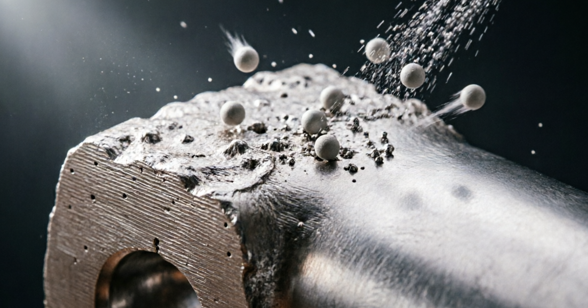
Coating adhesion on titanium SLM components is determined at the substrate preparation stage, not during coating deposition. A PVD film applied to insufficient profile or a contaminated surface will delaminate regardless of how carefully the coating is deposited. HVOF that meets specification on a properly profiled titanium surface will spall from a smooth substrate every time. This guide provides the complete surface preparation framework — Ra targets, blast protocols, cleanliness standards, and maximum coating intervals — for the four coating technologies most commonly applied to titanium SLM parts.
1. Why Surface Preparation Determines Coating Success
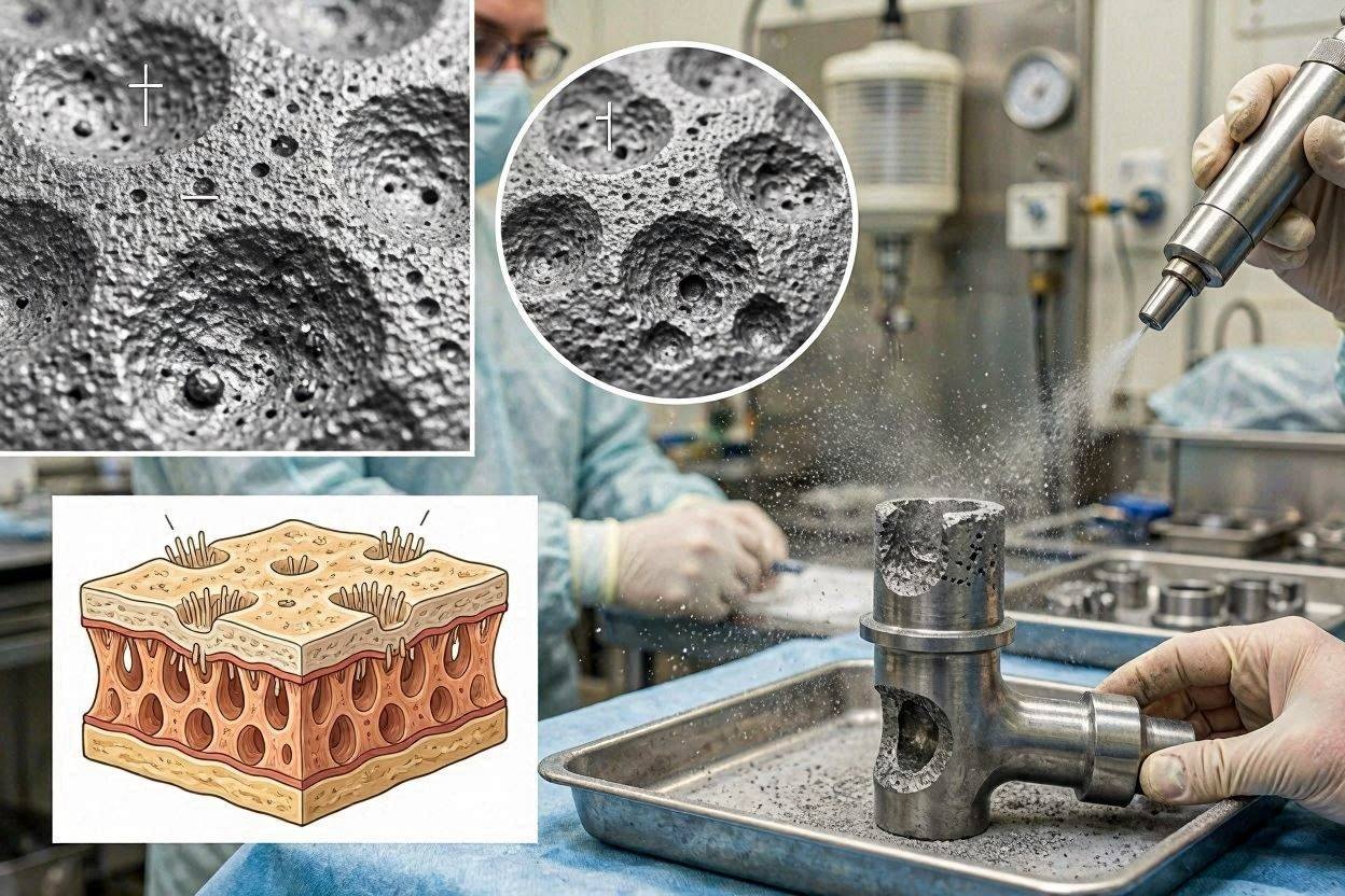
Coatings fail at their weakest point, which is almost always the substrate–coating interface. The interface quality depends on two independent factors: surface profile (which controls the mechanical interlocking area and coating film conformance) and surface cleanliness (which controls the quality of chemical or atomic bonding between coating and substrate atoms). Both factors must be correct; errors in either invalidate the other. A chemically clean titanium surface with the wrong Ra will produce consistent coating thickness but poor adhesion; a properly profiled surface with organic contamination or iron deposits will produce variable adhesion and premature delamination in service.
The profile and cleanliness requirements differ by an order of magnitude between coating types. PVD requires Ra 0.4–1.6 μm and near-perfect cleanliness. HVOF requires Ra 6–12 μm and Sa 2.5 (near-white) cleanliness. A blasting protocol calibrated for one cannot serve the other, and the protocols cannot be simply interpolated between these extremes. Each coating type requires its own validated blast specification. This article is part of the series on abrasive finishing for titanium SLM parts.
2. PVD Coatings: Fine Profile and Atomic-Level Cleanliness
Physical vapor deposition coatings (TiN, TiAlN, CrN, AlCrN, TiCN, and related hard functional films) are deposited in high vacuum (10⁻ῳ to 10⁻⁵ mbar) at 150–500°C. Adhesion depends primarily on atomic-level contact quality between coating atoms arriving at the substrate surface and the substrate atoms themselves. The substrate Ra target for PVD on titanium SLM: Ra 0.4–1.6 μm. This provides sufficient contact area increase over a perfectly smooth surface to improve adhesion without creating surface valleys deeper than the typical PVD film thickness (2–10 μm) that would produce unbonded bridging.
Blast protocol for PVD preparation: fine Al₂OΆ (mesh 120–180) or fine glass beads (mesh 150–200) at 40–55 PSI in a dedicated titanium cabinet, dry or wet process. Surface cleanliness: no organic contamination (confirmed by water break test), no free iron (ferroxyl negative), Sa 2.5 visual cleanliness. Maximum interval to PVD chamber loading: 4–8 hours in controlled atmosphere. Many PVD system operators include in-chamber argon ion sputter etch before deposition as a secondary cleaning step that compensates for minor re-oxidation during the preparation interval, but this does not replace blast preparation.
3. DLC Coatings: Surface Activation Protocol
Diamond-like carbon (DLC) films deposited by PECVD on titanium SLM are used for tribological applications in precision instruments and medical devices. DLC adhesion is exceptionally sensitive to substrate preparation: the titanium–DLC interface has lower intrinsic adhesion than metal–metal or ceramic–metal interfaces, making it the first failure point when preparation is inadequate. Substrate Ra target for DLC: Ra 0.2–0.8 μm. DLC film thickness is typically 1–5 μm, and surface features deeper than half the film thickness create stress concentration and delamination initiation sites.
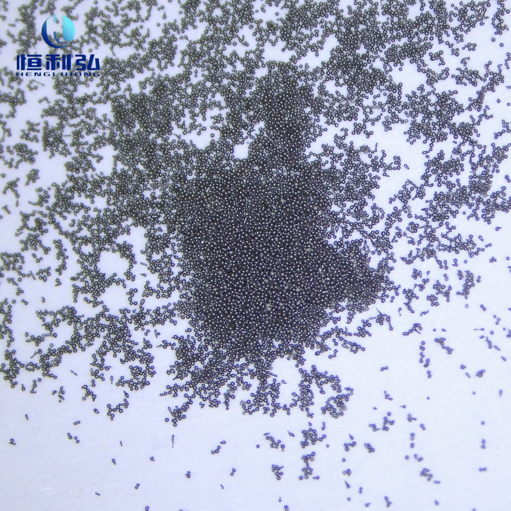
Wet blasting with fine zirconia or glass beads (mesh 200–280) at 25–40 PSI achieves Ra 0.2–0.6 μm on clean SLM titanium surfaces from Ra 1–5 μm starting conditions. In-system plasma sputter etch immediately before DLC deposition removes the thin surface TiO₂ layer that forms during handling and is standard practice for all DLC on titanium. Maximum interval to DLC deposition: 2–6 hours — DLC is the most re-oxidation-sensitive of the four coating types covered here, because of its reliance on high-quality surface activation.
3. HVOF Thermal Spray: Creating the Anchor Profile
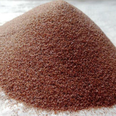
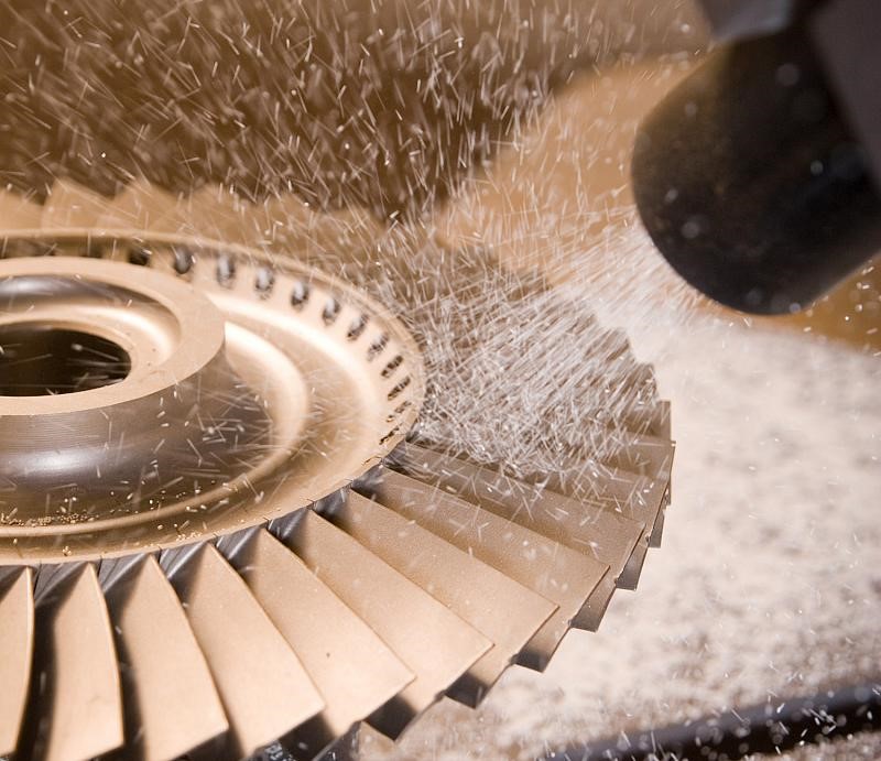
HVOF accelerates molten or semi-molten coating particles (WC-Co, MCrAlY, Inconel, and similar) to 300–700 m/s and impacts them onto the substrate. Adhesion depends primarily on mechanical interlocking between the rapidly cooled splats and the substrate surface asperities. The required anchor profile for HVOF on titanium SLM: Rz 50–120 μm (Ra approximately 6–12 μm). This requires angular Al₂OΆ at grit 20–60 (mean particle size 250–850 μm) at blast pressure 70–90 PSI in a dry process. The blasted surface must show Sa 2.5 (ISO 8501-1) or SSPC-SP 10 cleanliness: uniform gray-white metallic appearance, no mill scale, no organic contamination, no free iron.
The as-built SLM Ra (5–20 μm depending on build orientation) provides partial anchor profile on upskin surfaces but is directional (staircase steps) rather than random. A light blast pass with angular Al₂OΆ grit 60–80 at 50–60 PSI converts the directional staircase to a random anchor pattern even on surfaces with adequate as-built Ra, producing more uniform HVOF adhesion. On downskin surfaces (as-built Ra 15–25 μm), a reducing blast with fine Al₂OΆ brings the Ra into the 6–12 μm target window. Maximum interval to HVOF spraying: 8–12 hours.
4. Plasma Spray Preparation
Atmospheric plasma spray (APS) operates at lower particle velocities than HVOF and deposits coating splats with less kinetic energy. The anchor profile requirement for APS on titanium SLM: Rz 40–100 μm (Ra approximately 4–10 μm), achieved with grit 36–80 Al₂OΆ at 60–80 PSI. Sa 2.5 cleanliness is required. For titanium SLM parts with internal channels where plasma spray is required on internal surfaces, wet blasting with coarse Al₂OΆ slurry flowed through the channel is the only practical method for anchor profile creation on internal walls. Maximum interval: 4–8 hours.
| Coating Type | Ra Target | Blast Media | PSI | Cleanliness | Max Interval |
|---|---|---|---|---|---|
| PVD (TiN, TiAlN, CrN) | 0.4–1.6 μm | Al₂OΆ mesh 120–180 or glass mesh 150–200 | 40–55 | Sa 2.5 + zero Fe | 4–8 h |
| DLC (PECVD) | 0.2–0.8 μm | Zirconia or glass mesh 200–280 (wet) | 25–40 | Sa 2.5 + zero Fe + sputter etch | 2–6 h |
| HVOF (WC-Co, MCrAlY) | 6–12 μm (Rz 50–120) | Angular Al₂OΆ grit 20–60 | 70–90 | Sa 2.5 / SSPC-SP 10 | 8–12 h |
| Plasma spray (APS) | 4–10 μm (Rz 40–100) | Angular Al₂OΆ grit 36–80 | 60–80 | Sa 2.5 | 4–8 h |
5. Coating Interval: Managing Titanium Re-Oxidation
Titanium re-forms its TiO₂ passive oxide layer within milliseconds of blasting in ambient air. For most applications, this re-oxidation is protective and inconsequential. For PVD and DLC, where atomic bonding to the substrate governs adhesion, the thickening oxide layer degrades adhesion quality in a time-dependent manner. In the first 4–8 hours the re-oxide is thin (1–3 nm) and manageable by in-chamber ion cleaning; beyond 12 hours, oxide thickness increases significantly and adhesion is substantially compromised even with in-chamber etch.
Establishing and enforcing a documented maximum coating interval is a process control requirement, not an optional best practice. Parts that exceed the maximum interval must be re-blasted. Document the re-blast as a deviation with time-stamps, and record the new blast date/time as the start of the new coating interval. The maximum interval should be validated during coating process qualification by measuring adhesion (Rockwell indentation, scratch test, or pull-off test) on parts coated at 0, 4, 8, and 12 hours post-blast, and setting the specified maximum at the last time point that shows no statistical adhesion reduction.
Post-blast cleaning before coating entry is critical and time-sensitive. For the complete cleaning and passivation protocol, see our guide on post-blast cleaning, passivation, and inspection of abrasive-finished titanium SLM parts.
Preguntas frecuentes
PVD: 4–8 hours. DLC: 2–6 hours (most sensitive). HVOF: 8–12 hours. Plasma spray: 4–8 hours. These are upper limits under controlled low-humidity storage. Parts in higher humidity or handling environments should be coated sooner. Parts exceeding the maximum interval must be re-blasted before coating — no exceptions without written engineering disposition.
No. PVD requires Ra 0.4–1.6 μm (fine, uniform profile) while HVOF requires Ra 6–12 μm (aggressive anchor). HVOF blast parameters applied to a PVD zone produce too-rough a surface; PVD parameters applied to an HVOF zone produce insufficient anchor. When both coatings are required in different zones of the same part, mask each zone appropriately and apply the correct blast protocol to each zone sequentially. See our masking guide for multi-zone blast strategies.
Partially, on upskin surfaces (as-built Ra 4–8 μm). However, the as-built staircase profile is directional, while HVOF requires a randomly distributed anchor profile for uniform adhesion. A light blast with angular Al₂O₃ grit 60–80 at 50–60 PSI converts the directional staircase to a random pattern while maintaining adequate Ra. On downskin surfaces (as-built Ra 15–25 μm, exceeding the HVOF Ra maximum of 12 μm), a reducing blast with finer media is needed to bring Ra within specification before spraying.
For most HVOF coatings on titanium, the practical upper Ra limit is approximately Ra 12–15 μm (Rz 100–130 μm). Above this level, HVOF splats cannot fully conform to extremely deep surface valleys, leaving unbonded voids at the base of the deepest features. The safe operating window is Ra 6–12 μm, with the lower end preferred for maximum coating density and adhesion consistency.
Need Specialist Abrasive Media for Titanium SLM Finishing?
Jiangsu Henglihong Technology Co., Ltd. supplies the complete range of abrasive media for titanium SLM coating preparation — from grit 20 angular Al₂O₃ for HVOF anchor profiles to mesh 280 zirconia beads for DLC and PVD preparation. Contact our technical team for media specification, blast parameter guidance, and process support for your specific coating system.
Contact Our Technical TeamFiltros