Blasting AlSi10Mg Aluminum 3D Printed Parts for Anodizing and Coating Adhesion
AlSi10Mg (Al-Si10-Mg) is the most widely used aluminum alloy in SLM and laser powder bed fusion additive manufacturing — prized for its excellent printability, good mechanical properties, and low density. But SLM-processed AlSi10Mg presents surface finishing challenges that differ fundamentally from other AM alloys: the silicon-rich eutectic surface layer created during laser sintering hinders anodizing quality, the alloy’s low surface hardness creates a media-embedding risk with aggressive abrasives, and the complex microstructure responds differently to surface treatment than wrought aluminum alloys. This guide covers the complete blasting protocol for AlSi10Mg SLM parts — from media selection and process parameters to post-blast cleaning and anodizing preparation.
1. AlSi10Mg in Additive Manufacturing: Alloy Characteristics
AlSi10Mg is a near-eutectic Al-Si alloy with approximately 9–11% silicon and 0.2–0.45% magnesium by weight. Its composition was originally developed for casting applications, but its combination of low melting temperature range, high fluidity, and good laser absorptivity make it one of the most successfully adapted alloys for SLM/LPBF processing. As-built SLM AlSi10Mg achieves tensile strength of 380–450 MPa and yield strength of 220–280 MPa — comparable to conventionally produced AlSi alloys — with the freedom to produce complex internal geometries impossible in casting.
The alloy is used extensively for lightweight aerospace brackets, automotive heat exchangers, topology-optimized structural frames, drone components, and complex fluid manifolds. Parts are typically used either in the as-built plus stress relief condition, or after T6 heat treatment (solution anneal at 520°C + artificial aging at 160°C) for improved ductility and more uniform mechanical properties.
The properties of AlSi10Mg that matter for surface finishing are its low surface hardness (Vickers hardness HV ~130 in as-built condition), its silicon-rich surface microstructure, and its strong tendency to form a native aluminum oxide film (Al₂O₃) within seconds of exposure to air — which both protects the metal and complicates anodizing quality.
2. As-Built Surface Challenges Specific to AlSi10Mg
The as-built SLM AlSi10Mg surface has three characteristics that distinguish it from other AM alloys and require specific consideration in post-processing:
Silicon-Rich Surface Skin
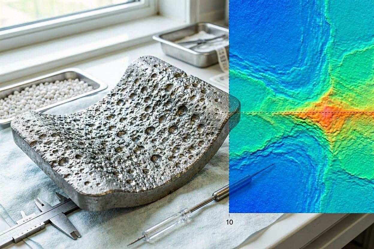
During SLM, the very outermost surface layer undergoes the most rapid solidification of any zone in the build. This ultra-rapid cooling traps more silicon in the surface region than in the bulk microstructure, creating a silicon-enriched “eutectic skin” at the part surface. This skin typically extends 10–50 µm below the surface and has a different electrochemical behaviour from the bulk AlSi10Mg — which is why parts anodized without prior surface preparation show colour banding, pinholes, and poor oxide uniformity. Blasting removes this problematic skin layer and exposes the more uniform sub-surface microstructure.
Partially Melted Powder Particles
Like all SLM alloys, AlSi10Mg surfaces carry partially melted powder particles (aluminium alloy particles, 15–45 µm diameter) adhered to the surface, particularly on side walls and down-skin surfaces. These particles contribute significantly to the as-built Ra (8–20 µm) and must be removed before anodizing — otherwise they create surface nodules in the anodic oxide layer.
Native Oxide Layer
Aluminum forms a native Al₂O₃ oxide layer of 2–10 nm thickness within seconds of air exposure. This layer is thicker and less uniform on as-built SLM surfaces (due to the high temperature and atmosphere variability during the build) compared to blasted or machined aluminum. Blasting removes the non-uniform as-built oxide and creates a clean metallic surface that, after chemical deoxidising, is ready for controlled anodizing electrolyte action.
3. Why Blasting Is Essential Before Anodizing AlSi10Mg
Anodizing AlSi10Mg without prior surface preparation produces a visually poor and technically inferior anodic oxide layer. The specific problems caused by anodizing the as-built SLM surface:
- Colour banding and variation: The as-built surface has varying silicon distribution between up-skin, side wall, and down-skin areas — each with different silicon density at the surface. These density differences create different anodizing rates, producing visible colour variation between faces after Type II anodizing, and especially after dyeing.
- Pinholes and oxide discontinuities: Partially melted powder particles and silicon nodules at the surface create points of localised current concentration during anodizing, producing pinholes and irregular oxide growth that compromise corrosion protection.
- Reduced coating thickness uniformity: Anodic oxide thickness varies significantly across the as-built surface, making it impossible to achieve consistent coating thickness for specifications requiring controlled oxide depth.
After glass bead blasting, the surface silicon distribution is homogenised by the removal of the silicon-rich skin layer, the partially melted particles are removed, and the surface texture is made uniform — allowing the anodizing process to produce a consistent, dense, properly adherent oxide layer across all part surfaces. In controlled trials, blasted AlSi10Mg samples consistently outperform unblasted samples in salt spray corrosion testing after Type II anodizing.
4. Media Selection for AlSi10Mg: What Works and What to Avoid
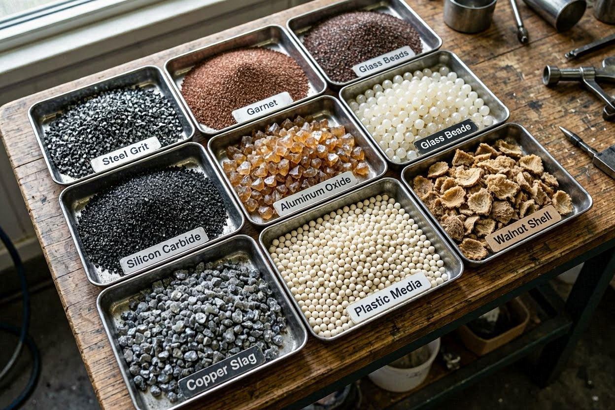
Glass Beads (Recommended for Anodizing Prep)
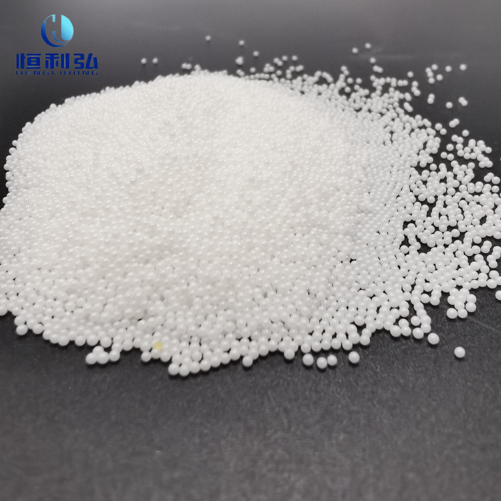
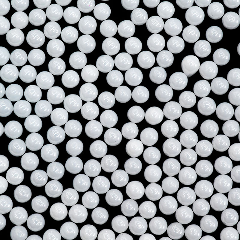
Glass beads in the 100–200 mesh range (75–150 µm) are the correct choice for blasting AlSi10Mg before anodizing. Their spherical shape minimises the embedding risk, and their hardness (Mohs 6 — harder than aluminum at Mohs 2.5–3 but much softer than Al₂O₃ at Mohs 9) is sufficient to remove the as-built oxide, partially melted powder particles, and silicon-rich skin without creating deep media embedment. The spherical peening action also introduces a slight compressive residual stress at the surface, which modestly improves fatigue resistance.
Key glass bead selection guidance for AlSi10Mg:
- 100–150 mesh: For parts with high as-built Ra (heavy side-wall texture, complex down-skin surfaces) where faster material removal is needed
- 150–200 mesh: Best all-purpose choice for most SLM AlSi10Mg blasting applications
- 200–250 mesh: For thin-walled parts, parts with fine features, or where the lowest achievable Ra is required before hard anodizing
Aluminum Oxide (Conditionally Acceptable)
Al₂O₃ grit can be used on AlSi10Mg for pre-coating applications (where a paint or powder coat anchor profile is required), but must be handled with care due to the embedding risk. Use 120–220 grit (not coarser), 45–55 psi (not higher), and single-pass exposure. Verify freedom from embedded media by SEM inspection for critical parts. Do not use Al₂O₃ for pre-anodizing surface preparation — embedded Al₂O₃ creates anodizing defects and is detectable as bright inclusions in the anodic oxide layer.
Steel Media — Never for AlSi10Mg
Steel shot and steel grit are inappropriate for AlSi10Mg. Beyond iron contamination risks, the high density and hardness of steel media at typical blast pressures will cause severe surface deformation and potential cracking of thin aluminum structures. Plastic media is acceptable for very delicate or thin-walled AlSi10Mg parts where even glass beads at minimum pressure pose a risk.
| Media | Use for AlSi10Mg | Mesh / Grit | Max Pressure | Notes |
|---|---|---|---|---|
| ガラスビーズ | ✓ Recommended — all applications | 100–200 mesh | 55 psi | Pre-anodizing standard; no embedding |
| Al₂O₃ grit | ⚠ Conditional — pre-coating only | 120–220 grit | 55 psi | Single pass; check for embedding |
| プラスチックメディア | ✓ Thin-wall / delicate parts | Various | 35 psi | Minimal Ra improvement |
| Steel shot/grit | ✗ Never | — | — | Iron contamination + structural damage |
5. Bead Blasting Protocol for AlSi10Mg
- Remove support structures. Mechanically remove all support structures before blasting. Post-support-removal areas will be treated with extra attention during blasting to remove EDM recast layers or mechanical cut marks.
- Inspect wall thickness. Identify walls below 1.5 mm and areas with thin features. These will be blasted at the minimum pressure in the range, or masked if they are precision features that must retain dimensional accuracy.
- Load glass beads 150–200 mesh. Verify media is clean, uncontaminated, and within the specified mesh range. Contaminated or overly degraded media produces inconsistent results and may introduce foreign material to the surface.
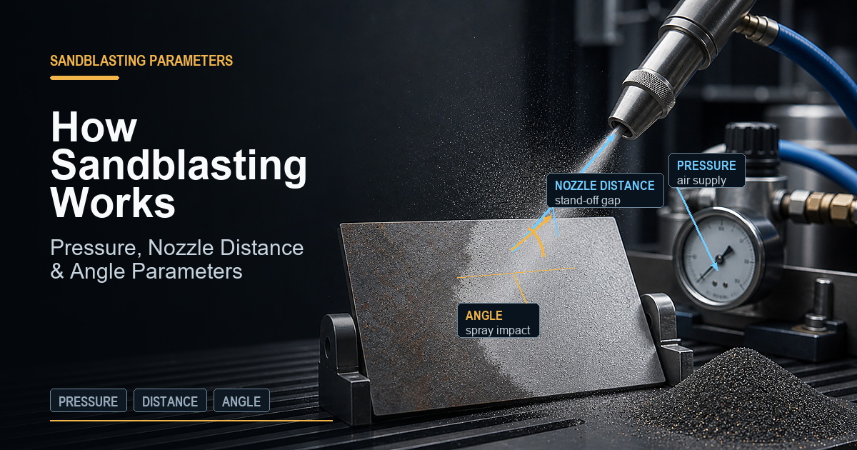
- Set pressure 35–55 psi. Start at 35 psi for thin-wall parts or complex features; increase to 55 psi for heavy-section areas. Direct pressure systems: reduce by 5–10 psi versus siphon systems.
- Blast with multi-axis coverage. Move the nozzle in overlapping parallel passes across each surface, targeting 95–100% coverage. Rotate the part to access all faces: up-skin, side walls, down-skin, and support-attachment zones. Maintain consistent standoff (8–12 inches) throughout.
- Targeted treatment of down-skin surfaces. Down-skin and support-attachment surfaces start with higher Ra (15–35 µm) and may need a second pass or slightly higher pressure to bring them to the same finish as up-skin surfaces. Use a focused nozzle angle of 60–75° on these areas.
- Blow off and clean. Compressed clean dry air blow-off immediately after blasting. For anodizing applications, proceed directly to alkaline degreaser cleaning within 30 minutes — do not leave blasted aluminum parts in ambient air for extended periods before anodizing prep.
6. Pre-Coating Blasting for Painted and Powder-Coated AlSi10Mg Parts
For AlSi10Mg parts that will be painted (liquid spray paint, epoxy primer, or polyurethane topcoat) rather than anodized, an Al₂O₃ blast profile is often preferred over glass beads because the angular grit creates a better mechanical anchor profile for organic coatings. The recommended approach:
- First pass: Glass beads 150–200 mesh at 40–50 psi — removes as-built oxide and powder particles, normalises surface
- Second pass: Fine Al₂O₃ 150–220 grit at 45–55 psi — creates angular anchor profile for coating adhesion (target Ra 3–5 µm)
- Coat within 4 hours of blasting — the activated aluminum surface is most receptive immediately after blast treatment
For powder coating, apply a zinc phosphate or chromate conversion coating (chemical treatment) between the blast and powder coat stages. This conversion coating improves conductivity (critical for electrostatic powder attraction) and provides an additional adhesion layer between the aluminum surface and the powder coat.
For thermal spray coatings (ceramic, cermet), use a coarser Al₂O₃ profile (60–80 grit at 60–80 psi) to create a rough anchor profile (Ra 6–10 µm) appropriate for mechanical keying of the spray deposit.
7. Dimensional Considerations and Thin-Wall Parts
AlSi10Mg SLM parts frequently feature thin-walled structures (1–3 mm wall thickness) enabled by the AM process and topology optimisation. Blasting thin-wall structures requires careful parameter management to avoid distortion or cracking.
Material removal rate: Glass bead blasting at 40–50 psi removes approximately 0.01–0.03 mm of material per pass from an AlSi10Mg surface. For parts with positional tolerances of ±0.1 mm or wider, this is negligible. For press-fit bores or precision mating surfaces with ±0.05 mm tolerances, measure before and after blasting and reduce blast exposure to the minimum needed for cleaning.
Distortion risk: Thin walls below 1.5 mm under direct pressure blasting at pressures above 40 psi can distort due to the peening compressive stress induced by glass bead impact. For walls in the 1.0–1.5 mm range, use maximum standoff (12–14 inches) and minimum pressure (30–35 psi) to reduce impact energy. For walls below 1.0 mm, mask the area or use plastic media at very low pressure.
Part fixturing: Support thin-walled parts appropriately during blasting to prevent vibration-induced movement that causes uneven coverage. Simple V-blocks, custom foam holders, or pin fixtures maintain part orientation without contacting critical surfaces.
8. Post-Blast Cleaning Sequence for Anodizing
The window between blast and anodizing is critical. Blasted aluminum oxidises within minutes in ambient air, and the new oxide layer — while very thin — can affect anodizing quality if the cleaning sequence is not completed promptly.
- Immediate blow-off: Remove all media with clean compressed air within 5 minutes of blasting completion.
- Alkaline degreaser: Immerse in or spray with alkaline degreaser (pH 9–11, 50–60°C) for 3–5 minutes. This removes surface oils, media dust, and residual process contamination. Rinse with DI water.
- Chemical deoxidiser: Immerse in a non-etch deoxidiser (ferric sulphate/nitric acid or chromic acid-free equivalent, per your anodizing specification) at room temperature for 1–2 minutes. This removes the thin native oxide layer that has formed since blasting. Rinse with DI water.
- Immediate transfer to anodizing tank: Parts should enter the anodizing tank within 10–15 minutes of the final DI water rinse. Do not allow parts to dry after deoxidising — the wet, oxide-free surface is the ideal starting condition for the anodizing electrolyte.
This sequence removes all contamination introduced by the blast process (media dust, handling contact, ambient particulate) and prepares a fresh, clean, reactive aluminum surface for controlled anodic oxide growth.
9. Quality Control and Inspection
- Visual after blasting: Uniform matte silver-grey surface across all faces. No shiny patches (unblasted areas), no black spots (oxidised areas from heat treatment), no loose media accumulation in recesses or channels.
- SEM/EDS for critical parts: For medical and aerospace AlSi10Mg parts, SEM energy-dispersive spectroscopy (EDS) confirms the absence of embedded media particles in the surface. Al₂O₃ particles would appear as bright, distinct inclusions in the SEM backscatter image against the aluminum matrix background.
- Ra measurement: Contact profilometer measurement confirms Ra is within the target range (1–4 µm for glass beads). Measure in at least three orientations on representative surfaces.
- Post-anodizing quality check: After anodizing and dyeing, inspect for colour uniformity across all faces. Significant colour variation between faces that were well-blasted indicates a problem in the anodizing process rather than blasting; uniform single-face colour variation across an entire up-skin or down-skin face suggests incomplete blasting coverage on that face.
For the complete metal AM blasting overview, see: Shot Blasting Metal 3D Printed Parts: SLM, DMLS, and EBM Post-Processing Protocol. For comparison with titanium alloy blasting requirements, see: Surface Finishing Ti-6Al-4V Titanium 3D Printed Parts: Blasting for Roughness Reduction and Fatigue Life.
よくある質問
Why does AlSi10Mg anodize unevenly if not blasted first?
AlSi10Mg contains approximately 10% silicon dispersed as eutectic Si particles throughout the aluminum matrix. During SLM processing, the rapid solidification creates a fine-scale microstructure where silicon is distributed non-uniformly at the surface — with higher silicon concentration at the outermost skin layer formed during laser scanning. Silicon does not anodize: it remains as metallic inclusions in the anodic oxide film, creating discontinuities, pinholes, and colour variation across the anodized surface. The distribution of silicon at the as-built surface is non-uniform due to the layer-by-layer scanning pattern, making colour variation even more pronounced. Blasting removes the outermost silicon-rich skin and mechanically homogenises the surface, allowing the anodizing current to distribute more evenly and produce a more uniform, denser anodic oxide layer.
Can Al₂O₃ media be used on AlSi10Mg without embedding risk?
Aluminum oxide media can be used on AlSi10Mg, but the embedding risk must be managed carefully. Al₂O₃ is significantly harder (Mohs 9) than AlSi10Mg (Mohs 2.5–3), so hard angular particles can become physically lodged in the soft aluminum surface under blast impact. The key controls are: use the finest appropriate Al₂O₃ grit (120–220 mesh), minimum effective pressure (45–55 psi), shortest effective exposure time (single pass), and the largest safe standoff distance (8–10 inches). After blasting, SEM inspection can confirm whether embedding has occurred. For anodizing applications, glass bead blasting is strongly preferred over Al₂O₃ because embedded particles create anodizing defects. Use Al₂O₃ on AlSi10Mg only when a pre-coating anchor profile is required and the coating system will cover any embedded media.
What anodizing type is most compatible with SLM AlSi10Mg?
Type II anodizing (sulphuric acid anodize, forming an oxide layer of 5–25 µm) is the most widely used and most compatible anodizing process for SLM AlSi10Mg. It produces acceptable corrosion resistance and dye uptake on blasted AlSi10Mg surfaces. Type III hard anodizing (forming 25–100 µm oxide layers) is more problematic on AlSi10Mg: the high silicon content creates non-uniform hard oxide growth, and the process can cause cracking or burning at silicon-rich areas. If hard anodizing is required for an SLM AlSi10Mg part, thorough pre-blast surface conditioning is mandatory, and the silicon content must be evaluated against the specific hard-anodizing chemistry. Some customers switch to wrought 6061 inserts press-fit into SLM parts for surfaces requiring hard anodizing.
How does blasting affect the fatigue life of AlSi10Mg SLM parts?
Glass bead blasting introduces a shallow compressive residual stress layer (typically 0.05–0.15 mm depth) in AlSi10Mg SLM parts, which modestly improves fatigue resistance. Literature values for fatigue life improvement from bead blasting of SLM AlSi10Mg range from 10–30% improvement in high-cycle fatigue strength compared to as-built conditions. The as-built tensile residual stress at the SLM surface is partially reversed by blasting, which accounts for most of the improvement. For more significant fatigue life improvement on AlSi10Mg, heat treatment (T6 or stress relief) combined with blasting is more effective than blasting alone. For maximum fatigue improvement, consider vibratory surface finishing or deep rolling after blasting.
What is the recommended post-blast cleaning sequence before anodizing?
The post-blast cleaning sequence for AlSi10Mg before anodizing: (1) Compressed clean dry air blow-off to remove all surface media and dust. (2) Ultrasonic cleaning in alkaline degreaser (pH 8–10, 45–60°C, 5–10 minutes) to remove any surface oils, media fragments, and process residue. (3) Rinse with deionised water at room temperature. (4) Light chemical deoxidiser etch (e.g., Sanchem 1000 or equivalent, 1–2 minutes at room temperature) to remove residual oxide and activate the surface for anodizing. (5) Final DI water rinse. Proceed immediately to anodizing after the final rinse — the activated aluminum surface oxidises in air and the activation window is short (typically 15–30 minutes). Do not allow parts to dry completely between deoxidising and anodizing.
Can blasted AlSi10Mg parts be powder coated directly?
Yes — bead-blasted or Al₂O₃-blasted AlSi10Mg provides an excellent substrate for powder coating. The key requirement is conductivity: AlSi10Mg with its native oxide is not sufficiently conductive for electrostatic powder gun attraction. Apply a chromate conversion coating (MIL-C-5541 or equivalent) or a zinc phosphate conversion before powder coating to improve conductivity and adhesion. Alternatively, use a conductive primer applied by spray before electrostatic powder application. The blast-produced surface texture (Ra 2–5 µm for glass beads, 3–7 µm for Al₂O₃) provides good mechanical anchor for both primer and powder coat. Cure temperature for powder coat (typically 160–200°C) is well within the safe range for AlSi10Mg mechanical properties.
Source Glass Beads for AlSi10Mg SLM Post-Processing
Jiangsu Henglihong Technology Co., Ltd. manufactures glass beads in mesh sizes optimised for SLM aluminum alloy post-processing, from 100 mesh for aggressive surface conditioning to 250 mesh for final pre-anodizing preparation. Contact our team for media specifications and sample evaluation for your AlSi10Mg production line.
Contact Our Technical TeamPublished July 2026 by Jiangsu Henglihong Technology Co., Ltd. — Specialists in industrial abrasive blasting media for additive manufacturing post-processing.
フィルター