Dimensional Accuracy and Tolerances After Ceramic Bead Blasting SLS Nylon Parts
Ceramic bead blasting removes material from SLS nylon parts — but in small, controlled, and well-characterised quantities. For the majority of SLS applications, the dimensional change is negligible relative to standard SLS tolerances. For tighter-tolerance parts, the same data that shows the change also shows the path to staying within specification. This article provides the material removal data, OD vs. ID comparison, tolerance implications by class, design compensation rules, and the first-article measurement protocol that should underpin any precision SLS depowdering operation.
1. What Ceramic Bead Blasting Actually Removes from SLS Parts
A common concern about introducing ceramic bead blasting into SLS post-processing is that it erodes the part and compromises dimensional accuracy. Understanding what is removed — and the mechanism by which it is removed — puts this concern in the correct proportions.
SLS nylon parts have a layered surface structure immediately after build. The outermost zone is the semi-sintered skin: a layer of partially fused nylon particles, typically 80–250 µm thick, that is bonded to the part surface but has lower density (approximately 70–85% of bulk nylon density) and lower cohesive strength than the fully sintered interior. This skin is what compressed-air blow-off fails to remove, and what ceramic bead blasting targets.
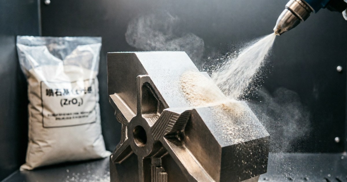
When a ceramic bead impacts the part surface, it delivers a compressive impulse that breaks the inter-particle bonds within the semi-sintered skin, dislodging the skin material from the surface of the bulk sintered part beneath. The material “removed” is therefore primarily the skin — lower-density, partially-sintered nylon that is not part of the functional part geometry — rather than the bulk sintered substrate. The bulk substrate material that is removed is a surface layer typically 10–40 µm deep, not the full skin thickness.
This distinction matters because the semi-sintered skin itself contributes to the as-built dimension of the part. Removing it produces a slight dimensional reduction — the part is slightly smaller post-blast than as-built — but this reduction is the removal of non-functional material that was always intended to be depowdered.
2. Material Removal Data by Bead Grade, Size, and Pressure
| Bead Grade / Size | Pressure | Cycle | External OD Removal | Internal ID Removal | Edge / Corner Removal |
|---|---|---|---|---|---|
| ZrO₂ 0.15–0.25 mm | 65 PSI | 7 min | 25–60 µm | 8–20 µm | 40–100 µm |
| ZS 0.15–0.25 mm | 62 PSI | 7 min | 20–55 µm | 7–18 µm | 35–85 µm |
| ZS 0.10–0.15 mm | 52 PSI | 10 min | 10–32 µm | 4–12 µm | 18–50 µm |
| ZS 0.10–0.15 mm | 45 PSI | 12 min | 8–22 µm | 3–9 µm | 14–38 µm |
| ZS 0.05–0.10 mm | 46 PSI | 16 min | 5–15 µm | 2–7 µm | 10–25 µm |
Edge and corner removal is higher than flat-face OD removal because edges receive concentrated blast impact from multiple angles simultaneously during the blast cycle. For parts where sharp external edges are a functional requirement, this higher edge removal must be accounted for in both the design compensation and the first-article measurement plan.
3. OD vs. ID: Why External and Internal Dimensions Behave Differently
External OD dimensions experience greater material removal than internal ID dimensions because the physics of blast coverage differs fundamentally between external and internal surfaces.
On external surfaces, the blast nozzle can be positioned to deliver direct, near-perpendicular impact to the surface. The bead arrives with full kinetic energy at near-optimal impact angle, maximising material removal per impact. External surfaces receive hundreds of impacts per unit area throughout the blast cycle.
Inside a bore, channel, or recessed feature, the geometry limits how the bead can arrive. Beads enter the feature, scatter off the internal walls, and exit — but the indirect, lower-angle impacts carry less effective material removal per impact. Blind features receive even less coverage than through-channels because beads cannot exit and must rely on ricochet impacts alone.
The practical result: OD removal is approximately 2–4× greater than ID removal for the same blast cycle. This means:
- External OD features shrink more per cycle than internal ID features grow per cycle
- Design compensation (if needed) targets external OD dimensions, not internal holes or channels
- Internal channel diameters are rarely affected significantly enough to require compensation at tolerances of ±0.2 mm or wider
4. Tolerance Implications by SLS Tolerance Class
| Tolerance Class | Typical SLS Application | Impact of Standard Blast | Action Required |
|---|---|---|---|
| ±0.3 mm and wider | Non-critical functional parts, visual models | Negligible (removal <20% of tolerance band) | No action; blast with standard protocol |
| ±0.2 mm | General functional SLS parts | Small (removal <30% of tolerance band) | No compensation; verify with first article |
| ±0.1 mm | Mating features, precision assemblies | Moderate (removal 10–60% of tolerance band for OD) | Use fine-bead low-pressure protocol; first-article measurement mandatory |
| ±0.05 mm | High-precision interfaces | Significant; removal approaches or exceeds tolerance band for OD | Ceramic bead blasting not recommended; mask tight features or use alternative finishing |
SLS nylon parts inherently carry build-to-build dimensional variation of approximately ±0.1 to ±0.2 mm from the sintering process itself. Specifying ±0.05 mm tolerances on as-built SLS parts — before any post-processing — is generally inappropriate for the process. Ceramic bead blasting adds a small, predictable, controllable dimensional change on top of this inherent SLS variation.
5. Design Compensation: When and How to Apply
Design compensation means adjusting the intended dimension in the CAD model upward (for OD features that will be blasted) so that the post-blast final dimension lands on the target. It is not always necessary — for most SLS tolerances of ±0.2 mm or wider, the blast-induced change is small enough that no compensation is needed.
Design compensation rules for ceramic bead blasted SLS parts
- External OD, ±0.2 mm tolerance or wider: no compensation needed
- External OD, ±0.1–0.15 mm tolerance, standard blast: add 20–40 µm to the intended dimension in the CAD model
- External OD, ±0.1–0.15 mm tolerance, fine-bead low-pressure blast: add 10–25 µm
- External sharp edges (acute angle features): consider adding 30–60 µm or applying a small design radius to prevent disproportionate blast removal
- Internal ID (holes, bores, channels), ±0.2 mm or wider: no compensation needed
- Internal ID, ±0.1 mm: measure first article without compensation; apply only if first-article data shows removal exceeding 50% of tolerance budget
Always verify compensation by first-article measurement before applying it to production. Compensation values are calculated from the data ranges in Section 2; actual removal on a specific part geometry may be at the low or high end of these ranges depending on feature size, blast angle, and coverage uniformity. Applying a compensation value from a reference table without verification can create a new dimensional non-conformance if the actual removal is lower than the range maximum used to derive the compensation.
6. First-Article Dimensional Qualification Protocol
The first-article dimensional qualification establishes whether the ceramic bead blast protocol produces acceptable dimensional outcomes for a specific part design. It must be performed for every new part design and whenever the blast protocol changes materially (bead grade, size, pressure, or cycle time).
- Baseline measurement (pre-blast): measure all reference dimensions on the first-article part before blasting, using calibrated calipers or CMM. Include at minimum: one external OD (longest or tightest-tolerance external dimension), one external edge dimension, one internal bore or channel diameter (if present)
- Blast at specified protocol: bead grade, size, pressure, nozzle, cycle time as documented
- Post-blast measurement: measure the same reference dimensions on the same part using the same instrument and technique as the baseline measurement
- Calculate removal: baseline − post-blast = material removal per surface per cycle. Record for each reference dimension separately
- Compare against tolerance budget: confirm that post-blast dimensions fall within the tolerance specification. If OD dimensions show removal exceeding 50% of the tolerance budget, consider fine-bead protocol or design compensation
- Approve and document: the qualified protocol, measurement data, and pass/fail criteria become the production process specification for this part
7. Documentation for Regulated Applications
SLS parts for medical devices (ISO 13485 / FDA 21 CFR Part 820), aerospace (AS9100 / NADCAP), and automotive safety applications (IATF 16949) require the blast process to be validated as a special process and documented in the manufacturing record.
The minimum documentation requirement for each production batch includes: part number and revision; ceramic bead grade, composition, and size range; blast cabinet type and qualification status; inlet pressure (PSI) measured at nozzle; cycle time; media charge age (cycles since last replacement or top-up); operator identification; and the dimensional measurement result on the qualification coupon for that batch.
Jiangsu Henglihong Technology Co., Ltd. provides Certificate of Conformance (CoC) documents, material data sheets (composition, density, hardness), and lot-specific PSD data for all ceramic bead grades. These documents support customer process validation dossiers under ISO 13485, AS9100, and equivalent quality management standards.
よくある質問
A standard blast cycle using ZS beads at 0.15–0.25 mm and 60–65 PSI for 7 minutes removes approximately 20–55 µm from external OD surfaces of PA12 SLS parts. This material is primarily the semi-sintered surface skin — not the bulk sintered nylon substrate. Internal ID dimensions are affected less: typically 7–18 µm per cycle. For tighter-tolerance applications, the fine-bead protocol (0.10–0.15 mm at 45–52 PSI) reduces OD removal to 8–22 µm, staying well within a ±0.1 mm tolerance budget.
Yes — internal ID dimensions experience approximately 2–4× less material removal than external OD dimensions under equivalent blast conditions. This is because blast coverage inside holes and channels is indirect and partial: beads enter, scatter off internal walls, and exit without the near-perpendicular direct impact that external surfaces receive. For most SLS part designs at tolerances of ±0.2 mm or wider, internal dimensions require no compensation. External OD features with ±0.1–0.15 mm tolerances may benefit from 10–40 µm of design compensation, verified by first-article measurement.
Yes, with appropriate protocol selection. For ±0.1 mm tolerances, use fine ZS beads at 0.10–0.15 mm, reduced pressure (45–52 PSI), and a single cycle. At these parameters, OD material removal is typically 8–22 µm — well within a ±0.1 mm tolerance band of 100 µm total. Verify by first-article dimensional measurement before production commitment, and document the protocol as a controlled special process. For tolerances tighter than ±0.05 mm, ceramic bead blasting is not recommended; consider masking tight-tolerance features during blasting.
For most SLS applications with tolerances of ±0.2 mm or wider, no compensation is needed — the blast-induced removal is small relative to the tolerance band. For external OD features with ±0.1–0.15 mm tolerances, adding 20–40 µm to the intended CAD dimension is a reasonable precaution with a standard blast protocol, reduced to 10–25 µm with a fine-bead low-pressure protocol. Internal ID features generally require no compensation unless first-article measurement shows otherwise. Always verify compensation values by first-article measurement — do not rely on tabulated values alone without confirming they apply to your specific geometry.
Related Articles in This Series
Return to the Ceramic Beads for SLS Powder Removal — Complete Guide for the full overview.
The companion quality metric — Ra data and measurement protocol for SLS depowdering QC.
How pressure and cycle time control the material removal rate from SLS parts.
Selecting finer beads is the primary lever for reducing material removal on tight-tolerance parts.
PA12-specific protocol with dimensional accuracy data for the most common SLS material.
Dimensional considerations for flexible SLS materials — deformation vs. material removal.
How media charge aging affects material removal rate and when to monitor more closely.
Need Dimensional Data for Your SLS Ceramic Bead Blasting Protocol?
Jiangsu Henglihong Technology Co., Ltd. provides ceramic blasting beads with full technical documentation and can advise on bead grade and size selection to meet specific dimensional tolerance requirements. Contact us with your SLS material, part geometry, and tolerance class.
Request Technical Supportフィルター