Abrasive Blasting SLS and MJF Nylon 3D Printed Parts: Depowdering, Deburring, and Surface Prep
Powder bed fusion processes — Selective Laser Sintering (SLS) and Multi Jet Fusion (MJF) — produce nylon parts with unique surface characteristics that differ from both FDM plastics and metal AM components. The sintered powder surface is granular, matte, and dimensionally consistent, but with Ra values of 8–20 µm that are incompatible with most dyeing, coating, or precision assembly applications without post-processing. Abrasive blasting plays two distinct roles in the SLS/MJF post-processing workflow: first as a depowdering tool to remove trapped surface powder, and second as a surface conditioning process that creates a uniform, dye-ready, coat-ready surface texture. This guide covers both stages in detail, with media selection tables, parameter specifications for PA12 and PA11, and quality control procedures.
1. SLS vs MJF: Surface Condition Differences
Although SLS and MJF both fuse nylon powder in a heated build chamber, their mechanisms differ in ways that produce distinct as-built surface conditions.
SLS (Selective Laser Sintering) uses a CO₂ laser to selectively sinter individual powder particles. The sintered surface consists of particles fused to each other and to the substrate, but with a visible granular texture where each individual powder particle (typically 45–90 µm for PA12) contributes to the surface topography. The result is a coarser, more open surface at Ra 12–20 µm with a natural-white or off-white appearance. Loose powder also remains adherent to the surface inside recesses and channels, requiring active depowdering before any secondary treatment.
MJF (Multi Jet Fusion) applies a liquid fusing agent across the entire powder bed, then irradiates with an infrared lamp to fuse agent-coated areas. The fusing agent chemistry creates a slightly smoother, more uniform surface bond at Ra 8–15 µm. However, MJF introduces its own surface challenge: the detailing agent, applied at part boundaries to prevent edge fusion, leaves a characteristic surface chemistry variation that appears as a mottled grey pattern on the as-built surface. This non-uniformity makes as-built MJF parts visually inconsistent and makes dye absorption uneven without pre-treatment.
| Property | SLS (PA12) | MJF (PA12) |
|---|---|---|
| Typical as-built Ra | 12–20 µm | 8–15 µm |
| As-built appearance | White/off-white granular matte | Grey mottled, darker core vs lighter skin |
| Trapped surface powder | Significant — requires active depowdering | Moderate — fused surface traps less powder |
| Ra after bead blasting | 2–5 µm | 1.5–4 µm |
| Dye absorption as-built | Uneven — powder texture affects uptake | Very uneven — agent chemistry creates patches |
| Dye absorption after blast | Uniform | Uniform |
| 機械的性質 | Slightly lower density, more isotropic | Slightly higher density, excellent isotropy |
2. Why Abrasive Blasting Is Essential in the SLS/MJF Workflow
For SLS and MJF nylon parts, abrasive blasting addresses several problems simultaneously that no other single post-processing method can resolve:
- Powder removal: SLS parts in particular retain loose and semi-adherent powder in surface texture features, channels, and internal cavities. Blast energy dislodges semi-adherent powder particles that compressed air alone cannot remove.
- Ra reduction: Reduces as-built Ra (12–20 µm for SLS; 8–15 µm for MJF) to 2–5 µm — within the range required for functional use and pre-coating applications.
- Surface uniformity: Creates a consistent, isotropic matte surface across all build orientations (top, side, bottom, overhang), eliminating the variation in appearance between faces that is inherent in as-built SLS/MJF parts.
- Dye preparation: Bead-blasted surfaces absorb industrial dyes uniformly, producing consistent colour across the entire part and eliminating the mottled appearance of MJF parts or the differential absorption of SLS top vs. side faces.
- Coating adhesion: Creates a micro-texture that provides mechanical keying for spray coatings, powder coat, and adhesive bonding, replacing the non-uniform as-built texture.
Abrasive blasting for SLS/MJF is a two-stage process: Stage 1 = depowdering (plastic media or compressed air); Stage 2 = surface conditioning (glass beads). Do not skip Stage 1 and proceed directly to glass bead blasting — you risk embedding loose powder into the surface and creating an irregular, contaminated surface texture.
3. Stage 1 — Depowdering: Removing Loose and Trapped Powder
The depowdering stage removes loose and semi-adherent powder from the part’s surface, channels, and internal cavities. For SLS parts, this is a critical and time-consuming step due to the large amount of unsintered powder surrounding and adhering to the part after the build cycle. For MJF parts, depowdering is less intensive but still required before surface conditioning.
Compressed Air Depowdering
The first depowdering step uses a high-velocity compressed air blast (not abrasive) to blow loose powder from all accessible surfaces. Use a handheld nozzle at 60–90 psi, directing air into cavities, channels, and recesses at multiple angles. For complex parts with internal channels, rotate the part through multiple orientations while blowing to let gravity assist powder extraction. This step should remove the majority of loose powder but will not clear semi-adherent powder from the sintered surface.
Plastic Media Blasting for Depowdering
After compressed air depowdering, semi-adherent powder particles that are physically bonded to the surface texture require abrasive impact to dislodge. Plastic blasting media (PMB — polyester or acrylic particles, hardness 2–4 Mohs) at 25–35 psi provides exactly the right energy level: enough impact to break loose powder adhesion without modifying the underlying sintered surface texture. Use a fine-particle PMB size matched to the scale of the surface features.
The PMB stage typically takes 2–5 minutes for a palm-sized SLS part, longer for parts with deep channels or complex internal geometry. After PMB blasting, all surface-adhered powder should be dislodged. Inspect with compressed air blow-off and visual check under good lighting.
Vibratory Depowdering (Alternative)
Vibratory depowdering systems — which use mechanical vibration to shake loose powder from parts — are commonly used at industrial SLS production scale. They are faster for high volumes but less effective on parts with blind channels. In facilities with vibratory depowdering, the plastic media blast stage may be skipped or abbreviated, proceeding directly from vibratory depowdering to glass bead surface conditioning.
4. Stage 2 — Surface Conditioning: Improving Ra and Uniformity
Once the part is fully depowdered, the glass bead surface conditioning stage can begin. This stage reduces Ra, creates surface uniformity across all build faces, and prepares the part for dyeing, coating, or direct functional use.
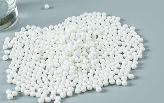
Glass beads (150–200 mesh, 75–105 µm diameter) at 35–50 psi are the standard media for SLS and MJF surface conditioning. The spherical beads impact the granular sintered surface in peening mode — deforming and flattening the irregular powder-particle texture into a more uniform surface — rather than cutting it. The result is a consistent matte surface where the build-orientation-dependent texture variation of the as-built part is minimised.
For MJF parts specifically, the glass bead conditioning stage has the additional effect of removing the surface chemistry variation (lighter/darker patches from the fusing and detailing agents) by mechanically abrading the very surface layer. After conditioning, MJF parts display a uniform, consistent grey-white colour that is appropriate for dyeing or painting with predictable results.
Typical Ra after glass bead conditioning: 2–5 µm (SLS) and 1.5–4 µm (MJF) — suitable for most functional parts, painted assemblies, and pre-dye preparation. For parts requiring Ra below 1.5 µm, a second conditioning pass with finer glass beads (200–250 mesh) at slightly lower pressure will reduce Ra further, typically to 1–2.5 µm.
5. Media Selection for Powder Bed Polymer Parts
| Stage | Media | Mesh / Type | Pressure (psi) | Objective |
|---|---|---|---|---|
| 1 — Depowdering | Compressed air | N/A | 60–90 | Loose powder removal from surfaces and cavities |
| 1 — Depowdering | Plastic media (PMB) | Acrylic or polyester | 25–35 | Semi-adherent powder removal from sintered surface |
| 2 — Conditioning | ガラスビーズ | 150–200 mesh | 35–50 | Ra reduction, surface uniformity, dye prep |
| 2 — Fine conditioning | ガラスビーズ | 200–250 mesh | 30–45 | Ra below 2.5 µm for precision surface requirements |
Do not use aluminum oxide grit on SLS or MJF nylon parts. Al₂O₃ is harder than the sintered nylon surface and creates deeper scratches than glass beads at equivalent grit size, leaving a coarser final Ra. It also risks embedding fine Al₂O₃ particles in the porous sintered surface, which can create contamination issues in dyed or coated parts.
6. Process Parameters for SLS and MJF
| パラメータ | SLS PA12 (Depowdering) | SLS PA12 (Conditioning) | MJF PA12 (Conditioning) |
|---|---|---|---|
| Media | Plastic media / compressed air | ガラスビーズ | ガラスビーズ |
| Mesh / size | — | 150-200 | 150-200 |
| Pressure | 25–35 psi | 35–50 psi | 35–50 psi |
| Standoff distance | 10–14 in | 8–12 in | 8–12 in |
| Nozzle angle | 45–75° | 60–90° | 60–90° |
| Coverage target | 100% of accessible surfaces | 98–100% | 98–100% |
| Typical cycle time (100×100×50 mm part) | 3–6 min | 3–6 min | 3–5 min |
7. Preparing SLS/MJF Parts for Dyeing and Coating
Dyeing Nylon Parts After Blasting
Industrial dyeing of SLS and MJF nylon parts uses aqueous acid dyes (similar to textile dyeing) applied by hot-dip immersion. Bead-blasted parts accept dye far more uniformly than as-built parts, for two reasons:
- The blast process creates a mechanically uniform surface with consistent surface energy and porosity, eliminating the chemistry variation left by the sintering or fusing process.
- Blasting removes the outermost surface layer where sintering has created a denser, less porous “skin” compared to the sub-surface — exposing a more uniform porous structure for dye penetration.
After blasting, the recommended dyeing sequence: rinse the part with clean water → immerse in heated dye bath (90–100°C for PA12, 80–90°C for PA11) → hold for 15–45 minutes depending on desired colour depth → remove and rinse with clean water → air dry. Black and dark colours achieve maximum uniformity and colour saturation with blasted surfaces. Pastel and light colours show less dramatic improvement from blasting but still benefit from the uniform surface.
Coating and Painting After Blasting
Bead-blasted SLS/MJF nylon presents an excellent substrate for painting. The uniform matte surface with Ra 2–5 µm provides good mechanical adhesion for spray primers and topcoats. Use a flexible primer formulated for plastics (such as an adhesion-promoting primer containing chlorinated polyolefin) to maximise coating adhesion on the nylon surface. Apply in thin coats to preserve fine surface details. Two-component polyurethane topcoats provide the best combination of adhesion, flexibility, and durability for load-bearing nylon parts.
For powder coating, nylon parts must first be coated with a conductive base coat (or dipped in conductive solution) since nylon is not inherently conductive enough for standard electrostatic powder application. Bead blasting creates the ideal surface for the conductive primer to bond to.
8. Material Variants: PA11, PA12-GB, and Filled Grades
PA11 (Polyamide 11)
PA11 is derived from castor oil (bio-based nylon) and is tougher and more ductile than PA12. As a blasting substrate, PA11 is more impact-resistant than PA12 and tolerates slightly higher blast pressures (up to 55 psi) without surface damage. The as-built surface Ra of SLS PA11 is similar to PA12 (12–18 µm); post-blast Ra achievement is also similar (2–5 µm). PA11 is commonly used in applications requiring higher elongation at break — flexible ducting, automotive fuel lines, medical device housings — where a smooth, durable surface is needed alongside mechanical performance.
PA12-GB (Glass Bead Filled)
PA12-GB contains glass microspheres dispersed throughout the nylon matrix, increasing stiffness and reducing thermal expansion. The glass content creates a harder surface than PA12 alone, and the glass beads exposed at the surface after sintering create a different micro-texture. Blasting PA12-GB requires slightly higher pressure (45–55 psi) to achieve equivalent surface conditioning to unfilled PA12. The resulting surface is slightly coarser but dimensionally more stable. PA12-GB parts are commonly used for dimensional jigs and fixtures where the improved surface finish from blasting aids in assembly and part inspection accuracy.
TPU Powder (SLS Flexible)
Some SLS systems process thermoplastic polyurethane powder for flexible end-use parts. SLS TPU surfaces are similar to SLS PA12 in as-built Ra but are softer and more elastic. Apply the same gentle blasting principles as for FDM TPU (plastic media or low-pressure fine glass beads at 20–35 psi) to avoid surface damage.
9. Quality Control and Inspection
- Complete depowdering verification: Before proceeding to surface conditioning, hold the part under good lighting and inspect all channels, recesses, and internal features for residual loose powder. Blow with compressed air and tap the part to dislodge any remaining loose powder. Surface conditioning cannot proceed reliably on a part with incompletely depowdered cavities.
- Visual surface uniformity: After glass bead conditioning, the surface should display a uniform matte appearance across all faces. Variation in texture between top faces (where the laser or fusing agent acted directly) and side faces should be minimised. Any remaining gloss patches or colour variation on MJF parts indicates incomplete conditioning coverage.
- Ra measurement: For dye-prep applications, profilometer measurement is usually unnecessary — visual check of uniformity is sufficient. For parts that will be coated or bonded, and where the specification requires Ra < 3 µm, verify with a contact profilometer on representative faces.
- Dimensional check: Glass bead blasting at standard SLS/MJF parameters removes less than 0.03 mm of material per pass. For parts with tolerances tighter than ±0.15 mm, perform pre- and post-blast dimensional verification on critical features.
For further reading on how blasting affects surface roughness measurements and how to interpret Ra data for AM polymer parts, see: Improving Ra and Rz on 3D Printed Parts: How Abrasive Blasting Reduces Surface Roughness. For FDM polymer blasting, see: Bead Blasting FDM 3D Printed Parts: Smoothing Layer Lines and Finishing Plastic Surfaces.
よくある質問
What is the difference between SLS and MJF surface finish before blasting?
SLS (Selective Laser Sintering) produces Ra values typically between 12–20 µm, with a coarser, more open granular texture formed by partially sintered PA12 or PA11 powder particles. MJF (Multi Jet Fusion) produces a slightly smoother as-built surface at Ra 8–15 µm due to the fusing and detailing agent chemistry that creates a more compact, bonded surface layer. However, MJF parts have a characteristic non-uniform grey mottled appearance that makes them visually inconsistent across faces. After bead blasting, both SLS and MJF reach Ra 2–5 µm with a uniform matte surface, at which point the visual and functional differences between the two processes are largely eliminated.
Do SLS parts need to be depowdered before abrasive blasting?
Yes — depowdering must precede abrasive blasting. Abrasive blasting alone cannot substitute for proper depowdering. Loose powder inside cavities and channels can only be removed with compressed air blowout, vibratory depowdering, and manual cleaning before any blast media is applied. If a part with significant trapped powder is placed directly in a blast cabinet, the blast media embeds loose powder into the surface rather than conditioning it, producing an irregular, contaminated surface. Always complete the depowdering stage before transitioning to the surface conditioning blast stage.
What blasting media is best for MJF nylon parts?
Fine glass beads in the 150–200 mesh range (75–105 µm) are the best single-stage media for MJF nylon. They produce uniform Ra reduction from the as-built 8–15 µm down to 1.5–4 µm while creating the consistent matte surface that accepts industrial dyes and coatings evenly. For parts where depowdering is also needed (trapped powder in channels), use plastic blasting media in a first stage to gently clear powder before the glass bead finishing stage. Avoid aluminum oxide grit — its angular shape produces a coarser surface texture than glass beads at equivalent grit size, and there is no advantage for nylon applications.
Can abrasive blasting prepare SLS/MJF parts for dyeing?
Yes — abrasive blasting is the recommended surface preparation step before dyeing SLS and MJF nylon parts. As-built nylon surfaces absorb dye unevenly because the surface contains areas of varying density and powder adhesion. After bead blasting, the surface is uniformly conditioned with consistent micro-texture and porosity, producing even dye uptake across all faces and build orientations. The bead-blasted surface also eliminates the visual difference between upward-facing and downward-facing surfaces that is otherwise visible after dyeing as-built parts. For deepest and most uniform colour, blast followed by hot-dip dyeing (typically in a boiling aqueous dye solution for 15–45 minutes) produces the best results.
How does abrasive blasting affect the dimensional accuracy of SLS/MJF nylon parts?
Bead blasting at standard SLS/MJF parameters (35–50 psi, glass beads 150–200 mesh) removes a very thin layer of material — typically less than 0.02–0.05 mm per pass. For most SLS and MJF parts, which typically have dimensional tolerances of ±0.2–0.3 mm, this material removal is negligible. For precision fits requiring ±0.1 mm or tighter, perform a dimensional baseline measurement before blasting, validate material removal on coupons at your specific parameters, and adjust blast duration accordingly. The primary dimensional effect of blasting is surface peak removal, not bulk material loss.
Why do SLS parts sometimes show darker and lighter patches after blasting?
This is a common observation on natural (undyed) SLS PA12 parts. The variation in colour after blasting reflects differences in sintering density across the part. Areas closer to the outer surface received more laser energy during sintering and formed a slightly denser, harder skin; areas in transition zones or near support boundaries may have slightly lower density and different surface response to blasting. These variations are intrinsic to the SLS process and are also present in the as-built part — blasting makes them more visible by creating a uniform matte surface rather than masking them with the loose powder coating present on as-built parts. Dyeing after blasting is the most effective way to achieve uniform appearance.
Source Blasting Media for SLS and MJF Post-Processing
Jiangsu Henglihong Technology Co., Ltd. manufactures glass beads and plastic blasting media used in professional SLS and MJF post-processing operations worldwide. Our technical team can advise on two-stage depowdering and conditioning workflows for your specific nylon grades and production volumes.
Contact Our Technical TeamPublished July 2026 by Jiangsu Henglihong Technology Co., Ltd. — Specialists in industrial abrasive blasting media for additive manufacturing post-processing.
フィルター