Ceramic Bead Blasting TPU Flexible SLS Parts: Gentle Depowdering Without Deformation
Flexible SLS materials — TPU, elastomeric nylon, and similar Shore A 70–95 grades — are the most challenging category for ceramic bead depowdering. Unlike rigid PA12 or PA11, these materials compress and deform under bead impact rather than holding position. Getting them clean without deforming walls, collapsing lattice cells, or permanently rounding sharp features requires a completely different protocol: lower pressure, finer beads, shorter cycles, careful fixturing, and disciplined mid-cycle inspection.
1. The Depowdering Challenge for Flexible SLS Materials
Thermoplastic polyurethane (TPU) SLS parts bring capabilities that rigid nylon cannot match: vibration damping, compressible cushioning, integrated seals, flex-and-return joints, and impact absorption in a single printed body. The same elastomeric properties that make these parts commercially valuable also make them fundamentally more difficult to depowder than rigid SLS materials.
After a TPU SLS build, the part surface carries the same three residue categories as PA12: loose powder in internal features, caked powder in compressed geometry, and a semi-sintered skin bonded to all external surfaces. But the strategy for removing this powder must account for a part that bends, compresses, and deforms under the forces applied during cleaning — forces that would be negligible on a rigid PA12 equivalent.
The consequences of an incorrect TPU blast protocol are visible and irreversible: lattice cell walls that should be cylindrical become faceted or collapsed; sharp edges that should be crisp become permanently rounded; thin membranes that should flex freely become rippled or creased. Unlike PA12 where over-blasting primarily increases Ra and reduces dimensions slightly, over-blasting TPU produces geometric distortion that fails the part entirely.
2. How TPU SLS Parts Respond to Bead Impact
Understanding the physical mechanism of TPU deformation under blast impact is the prerequisite to designing a protocol that avoids it.
When a ceramic bead strikes a rigid PA12 surface, the bead transfers its kinetic energy to the surface over a very short contact time and the surface deforms elastically by micrometres before springing back. The bead bounces; the surface is unaffected structurally. The energy transferred dislodges the adherent powder skin.
When the same bead strikes a Shore A 85 TPU surface at the same velocity, the surface does not spring back immediately — it compresses visco-elastically under the bead, absorbing a much larger fraction of the kinetic energy into deformation rather than transmitting it to the powder skin. The impact zone sinks inward during contact; adjacent material is pulled laterally; the bead rebounds with less energy than it struck with; and the surface, while not permanently damaged by a single impact, has experienced a larger deformation than PA12 would.
The cumulative effect of thousands of impacts at too-high energy is where permanent deformation occurs. Each high-energy impact incrementally cold-works the TPU surface, progressively rounding edges, flattening ribs, and collapsing fine features. The threshold at which cumulative deformation becomes irreversible depends on Shore hardness, wall thickness, and part geometry.
3. Ceramic Bead Grade and Size Selection for Flexible SLS
Two variables drive the per-impact energy applied to TPU: bead density (a property of the ceramic grade) and bead velocity (controlled by blast pressure). The most effective approach for flexible SLS is to use the lowest practical bead density while maintaining adequate cleaning energy — which means selecting the ceramic grade that is just hard enough to dislodge the semi-sintered skin at reduced pressure.
| Bead Grade | 密度 (g/cm³) | Recommended TPU Application | Pressure Range |
|---|---|---|---|
| Zirconia-Silicate (ZS) | 3.8–4.0 | Shore A 82–95 TPU, walls ≥ 1.5 mm | 35–45 PSI |
| Alumina-Silicate | 2.4–2.7 | Shore A 75–85 TPU, walls 1.0–2.0 mm | 32–42 PSI |
| Pure ZrO₂ | 5.4–5.6 | Not recommended for flexible SLS | — |
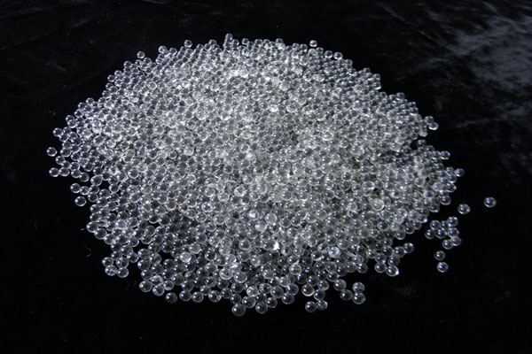
Bead size: always use the fine end of the range for flexible SLS. Fine beads (0.05–0.15 mm) carry less kinetic energy per particle than coarser beads, which is the key lever for reducing deformation risk. The trade-off — longer cycle time — is acceptable for flexible SLS parts, which are typically higher-value items where the cost of deformation-caused rejection exceeds the cost of a longer blast cycle.
The internal channel sizing rule (bead diameter ≤ 1/4 of channel opening) applies to flexible SLS just as for rigid — with the additional note that channels in TPU parts may partially compress closed under blast pressure if walls are thin, so choose the smallest bead size that still exits the channel rather than the largest that can enter.
4. Low-Pressure Protocol: Shore A 85–95 TPU
Shore A 85–95 represents the majority of TPU SLS production — materials that are noticeably flexible compared to nylon but that still maintain enough stiffness to hold their geometry under moderate external force. These parts can be blasted with ceramic beads at significantly reduced pressure with good results.
| Feature | Wall Thickness | Bead Grade / Size | Pressure | Cycle Duration |
|---|---|---|---|---|
| Standard body (Shore A 88–95) | ≥ 2.5 mm | ZS 0.10–0.15 mm | 38–45 PSI | 3–5 min per cycle |
| Moderate body (Shore A 85–92) | 1.5–2.5 mm | ZS 0.08–0.12 mm | 33–42 PSI | 2–4 min per cycle |
| Fine lattice (Shore A 85–95) | Strut ≥ 1.5 mm | ZS 0.05–0.10 mm | 30–38 PSI | 1.5–3 min per cycle |
| Channels < 1 mm | Body ≥ 2 mm | ZS 0.05–0.08 mm | 30–36 PSI | 2–4 min per cycle |
Use a suction-feed cabinet for all TPU blasting. Suction-feed delivers lower blast velocity at equivalent inlet pressure than pressure-feed, providing a more forgiving process window. For Shore A 85–95 parts where the wall structure can tolerate somewhat more energy, pressure-feed can be used at 8–12 PSI lower than the suction-feed guideline values — but suction-feed is strongly preferred until the protocol is well-established.
5. Very-Low-Pressure Protocol: Shore A 75–85 TPU
Very flexible TPU materials — Shore A 75 to 85 — require an even more conservative approach. At these hardnesses, the material compresses significantly under relatively modest blast impact, and the risk of permanent deformation is present even at the lower end of the standard flexible SLS pressure range.
Very-low-pressure ceramic bead protocol for Shore A 75–85 TPU
- Bead grade: Alumina-silicate (lowest density in the ceramic family, 2.4–2.7 g/cm³) at 0.05–0.10 mm
- Blast pressure: 28–36 PSI — use a calibrated regulator; do not estimate
- System: Suction-feed only
- Cycle duration: 1–2 minutes per cycle; maximum 3 cycles before rest and inspection
- Standoff distance: 120–160 mm (increased vs. standard to further reduce impact energy)
- Angle: 45–60° off-perpendicular to part surface, to reduce direct impact energy while maintaining coverage
- Inspection: After every single cycle; deformation is the primary reject criterion
At Shore A 75–80 and below, there is a genuine question of whether ceramic bead blasting is the right depowdering method at all. For very fine geometry or very soft materials, manual compressed-air depowdering combined with vibration (ultrasonic or mechanical) may deliver better results with less deformation risk. Assess on a part-by-part basis.
Side-by-side comparison of ceramic bead and plastic media performance on flexible SLS materials — decision framework for Shore A below 82.
6. Multi-Cycle Approach and Mid-Cycle Inspection
The single most important operational rule for TPU SLS ceramic bead blasting is: never run a single extended cycle. Unlike PA12 where a single 8-minute cycle is the standard, TPU requires multiple short cycles with inspection between each one.
The multi-cycle approach serves two purposes. First, it limits the cumulative impact energy in any single blast session, preventing localized over-blasting on exposed geometry. Second, it allows mid-cycle inspection to catch deformation early — before it becomes irreversible — and to redirect coverage to areas that still show residual powder.
Standard multi-cycle inspection protocol for TPU SLS
- Run Cycle 1 (1.5–3 min at protocol pressure)
- Remove part from cabinet; blow clean with compressed air
- Inspect under bright directional light for: deformation of features; completeness of powder removal by area; surface texture uniformity across all faces
- If no deformation and powder remains: continue to Cycle 2
- If deformation observed: stop; document failure; adjust pressure down 4–6 PSI and re-qualify on next part
- If clean: proceed to downstream operations
Rotate the part between cycles to distribute blast impact across all surfaces. A part that was blasted from the top in Cycle 1 should be blasted from the side in Cycle 2, and so on. This prevents any single face from receiving disproportionate cumulative impact.
7. Fixture and Support Design for Flexible SLS Blasting
Flexible SLS parts that are not fixtured during blasting will move, flex, and rotate under the blast plume, producing uneven coverage and potentially deforming unsupported sections. Effective fixture design for TPU SLS blasting follows different principles than for rigid PA12:
- Distribute support across the widest possible base area — a single-point support concentrates reaction force; a distributed cradle spreads it across the part’s natural contact surface
- Do not over-constrain flexible features — clamping a flexible joint rigidly during blasting prevents it from absorbing impact through its natural compliance; leave intentionally flexible sections free within their design range while supporting the rigid body
- Use soft fixture material — aluminium or steel fixtures with hard edges can deform soft TPU parts at the fixture contact points under blast pressure; use rubber-lined fixtures or soft PA12 SLS cradles for flexible SLS parts
- Design for multi-position access — a single fixture position rarely exposes all surfaces; design fixtures that allow the part to be repositioned between cycles with minimal handling
8. Surface Finish Outcomes on TPU SLS After Blasting
Surface finish Ra on TPU SLS parts after ceramic bead blasting is higher and more variable than on rigid nylon, due to the surface compliance effect under bead impact. The Ra values below reflect outcomes on Shore A 85–95 TPU at recommended protocol parameters:
| Surface Orientation | As-Built Ra | After ZS 0.10–0.15 mm / 38–42 PSI |
|---|---|---|
| Horizontal (top face) | 14–20 µm | 9–15 µm |
| Side / angled | 20–28 µm | 12–20 µm |
| Downward-facing | 16–22 µm | 10–17 µm |
Post-blast Ra on TPU is 3–5 µm higher than on equivalent rigid PA12 at the same bead size and pressure range. This is inherent to the material’s compliance and cannot be eliminated within the safe-pressure window. For TPU SLS parts, the primary quality outcome of blasting is completeness of powder removal そして surface uniformity, not absolute Ra minimization — Ra values in the 9–20 µm range are normal and acceptable for most flexible SLS applications.
Comprehensive Ra and Rz dataset across all SLS materials and bead grades, with measurement protocol templates.
9. Ceramic Beads vs. Plastic Media for Flexible SLS
The question of whether to use ceramic beads or plastic media (acrylic, melamine) for flexible SLS depowdering comes down to a specific trade-off: impact gentleness vs. cleaning effectiveness.
Plastic media (density ~1.2–1.6 g/cm³) delivers less kinetic energy per particle than ceramic ZS (3.8–4.0 g/cm³) at the same blast velocity. For very soft TPU (Shore A 75–80), this lower impact energy is the safety margin that prevents deformation — and plastic media is the better choice.
But for Shore A 82–95 TPU, ceramic beads at properly reduced pressure (33–45 PSI) still deliver more cleaning effectiveness than plastic media at equivalent pressure. This is because ceramic’s higher density converts velocity to impact energy more efficiently: at 38 PSI, a ZS bead arrives at the semi-sintered skin with 2.5× the kinetic energy of an acrylic bead at the same velocity. That energy differential is the difference between effective skin removal and a surface that looks clean under casual inspection but still carries adherent powder contamination.
Recommendation: use ceramic ZS beads for Shore A 82–95 TPU at reduced pressure. Switch to plastic media only for Shore A 75–80 or softer, or for extremely delicate geometry where even the lowest ceramic bead protocol causes measurable deformation.
よくある質問
For Shore A 85–95 TPU with wall thicknesses above 2 mm, a blast pressure of 35–45 PSI in a suction-feed cabinet is the recommended starting range. Run in cycles of 2–4 minutes and inspect between each for deformation of walls, collapse of lattice cells, or rounding of sharp features. If any deformation is observed, reduce pressure by 5 PSI and re-qualify on the next part. For walls below 2 mm or lattice struts below 1.5 mm, start at 33–38 PSI with very fine beads (0.05–0.10 mm).
Yes — the same suction-feed blast cabinet handles both materials. No media change is needed if you are using ZS ceramic beads for both PA12 and Shore A 85–95 TPU. The key change is reducing inlet pressure from the PA12 range (55–75 PSI) to the TPU range (30–45 PSI) — a simple regulator adjustment. After processing TPU, blow the cabinet clear of any remaining TPU powder before returning to PA12 production, as TPU powder residue is heavier and stickier than PA12 powder and may affect surface finish on subsequent PA12 runs if left in the chamber.
Blast lattice structures at the lowest pressure in your safe range (30–35 PSI for Shore A 85–95), using fine beads (0.05–0.10 mm) and very short cycles of 1.5–2.5 minutes. Rotate the part between cycles to distribute impact evenly across all lattice faces. Inspect lattice cell shape under magnification after each cycle — this is the primary deformation indicator. If lattice cells are compressing or deforming, reduce pressure and extend total cycle count rather than increasing pressure to speed up cleaning. For lattice interiors that cannot be reached by ceramic beads at any safe pressure, compressed-air blow-off after the external blast is the practical supplement.
For Shore A 85–95 TPU at 30–38 PSI, ceramic bead blasting with ZS media at 0.05–0.10 mm is generally safe for wall thicknesses of 1.2 mm and above. For walls of 0.8–1.2 mm, reduce pressure to 28–32 PSI and limit cycles to 1–2 minutes each. For walls below 0.8 mm on flexible TPU, consider manual compressed-air depowdering as an alternative — the deformation risk from any practical ceramic bead protocol outweighs the cleaning benefit at this wall thickness.
Related Articles in This Series
Part of the complete series on ceramic bead SLS depowdering. Return to the Ceramic Beads for SLS Powder Removal — Complete Guide for the full overview.
Full protocol for the dominant rigid SLS material — bead selection, pressure, Ra data.
Bio-based PA11 protocol and fixture requirements for flexible PA11 assemblies.
When plastic media outperforms ceramic for the softest flexible SLS materials.
Complete bead size reference — fine-bead selection for delicate TPU geometry.
Process parameter guide across all SLS materials — qualification methodology.
Ra data across all SLS materials including flexible grades — measurement protocol.
Get the Right Ceramic Beads for Flexible SLS Depowdering
Jiangsu Henglihong Technology Co., Ltd. supplies fine-grade zirconia-silicate and alumina-silicate ceramic blasting beads from 0.05 mm to 0.60 mm. Tell us your TPU Shore hardness, wall geometry, and geometry complexity — we will recommend the optimal grade and size for your application.
Request Samples & Technical Guidanceフィルター