Ceramic Beads for Orthopedic Implant Surface Treatment: A Complete Guide
Key takeaways: Ceramic bead blasting creates reproducible micro-roughness that directly drives bone-implant interlock. Getting the media, pressure, standoff, and validation right determines whether a hip stem or spinal cage integrates predictably. This article walks through how to select ceramics, dial in parameters within validated windows, avoid common contamination failures, and align with ISO/ASTM frameworks—without marketing fluff.
1. Why Surface Treatment Determines Implant Survival
If you’ve spent time on a manufacturing floor that produces hip stems, knee femoral components, or interbody cages, you know the surface isn’t cosmetic. A smooth metal finish can fail mechanically—fibrous encapsulation rather than direct bone apposition. Without controlled roughness, the implant doesn’t get the mechanical interlock necessary for primary stability, and secondary osseointegration stalls. That’s what drives us toward blasting, and increasingly toward ceramic bead media.
Surface treatment engineers usually juggle three targets: surface roughness (typically Ra, Rz, or Sa), topography isotropy, and chemical cleanliness. Ceramic bead blasting delivers uniform compressive stress in the near-surface zone while producing a micro-texture that osteoblasts recognize as “bone-like.” In titanium and cobalt-chrome alloys, a well-executed ceramic blast process hits Ra windows between roughly 2 and 6 µm—high enough to anchor cells, low enough to avoid crack initiation sites.
I’ve seen too many teams treat blasting as a quick “roughen it and move on” step. That approach causes scrap, regulatory questions, and late-stage fatigue failures. Blasting is a core manufacturing process, not a pre-clean. When you swap from glass beads to high-purity alumina, you change everything: dust generation, embedding risk, nozzle wear, and the validation burden.
This guide focuses on ceramic beads specifically because they’ve become the go‑to for implants requiring repeatable roughness, clean chemistry, and documented mechanical performance. The rest of the industry is shifting away from silica-containing media for obvious biocompatibility reasons. If you’re still running glass on load‑bearing devices, it’s time to review your risk file.
2. What Ceramic Beads Actually Are in Orthopaedic Blasting
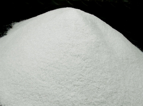
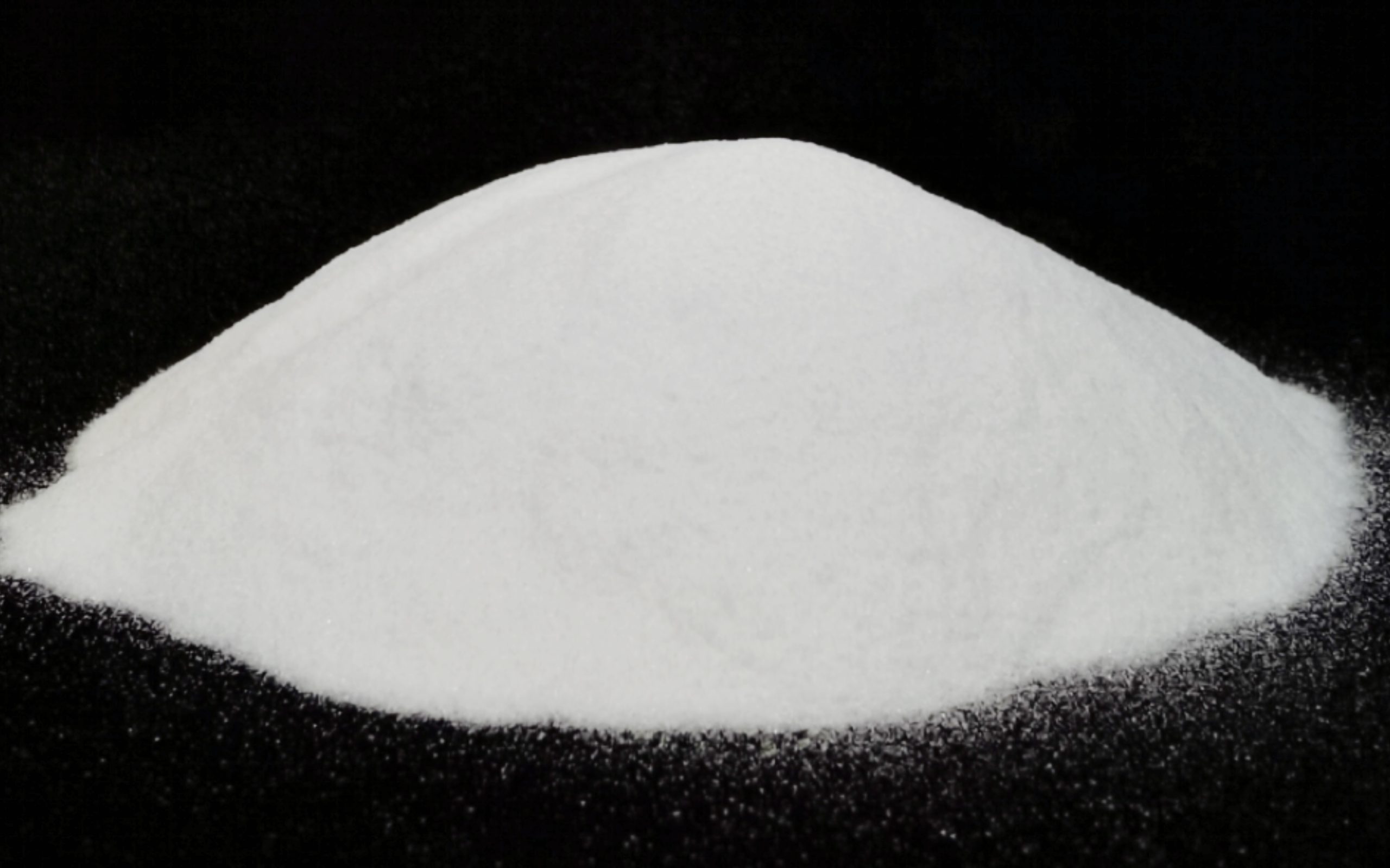
In orthopaedic context, “ceramic beads” means engineered, high‑hardness particles—usually spherical or angular—made from alumina (Al₂O₃), zirconia (ZrO₂), zirconia‑toughened alumina (ZTA), or hydroxyapatite (HA). They’re not the same as generic abrasive grit. Bead shape, size distribution, and chemical purity are controlled to levels that satisfy ISO 13385 and relevant ASTM standards.
Typical bead diameters for implant work fall between 50 and 350 µm, though you’ll see applications down to 25 µm for delicate additive‑manufactured lattice structures and up to 500 µm for aggressive macro‑roughness on cementless stems. The term “bead” often implies a spherical morphology that produces dimpled surfaces with few sharp craters, but we also use angular ceramic “grit” for higher cutting action—both fall under ceramic blasting media.
Why ceramics? The hardness values matter. Alumina around 9 Mohs (1900–2100 HV), zirconia slightly lower but tougher. That hardness lets you work‑harden the implant surface while removing a controlled amount of substrate. You get the beneficial compressive residual stress without excessive material removal, which is critical when working with thin‑walled additively manufactured lattice cups or PEEK‑optima cervical spacers.
A practical note: Don’t assume “ceramic” equals “contamination‑free.” Low‑grade alumina beads can contain silica, iron oxide, or titania impurities that transfer to the implant surface. For ASTM F67 unalloyed titanium or F136 Ti‑6Al‑4V, an iron inclusion above a few ppm can act as a galvanic trigger. That’s why the Guide to selecting ceramic bead suppliers emphasizes full material certification, not just a particle size report.
3. Engineering Ceramics: Alumina, Zirconia, Hydroxyapatite, and Bioactive Blends
Choosing the right ceramic media isn’t a one‑size‑fits‑all decision. It’s a trade‑off between hardness, toughness, embedding risk, cost per kilo, and the final biological response. Below is a reference matrix I use when qualifying a new implant project. This comparison is drawn from material properties that are widely published, combined with process experience on typical substrate alloys.
| Материал | Typical hardness (HV) | Fracture toughness | Best for substrate | Primary risk | Approx. media cost |
|---|---|---|---|---|---|
| Alumina (99.6‑99.9% Al2O3) | 1900‑2100 | 3‑4.5 MPa·m1/2 | Ti‑6Al‑4V, CoCr, 316L | Embedding if pressure too high or beads fracture | Умеренный |
| Zirconia (Y-TZP) | 1200‑1350 | 6‑10 MPa·m1/2 | CoCr, tougher substrates, thin walls | Lower material removal rate; may require longer cycle | Высокий |
| ZTA (Zirconia‑Toughened Alumina) | 1500‑1700 | 4.5‑6 MPa·m1/2 | Hybrid designs, AM lattices | Consistency across batches; fewer suppliers | Высокий |
| Hydroxyapatite (HA) beads | 400‑500 (relatively low) | < 1 MPa·m1/2 | Final bioactive touch after primary blasting | Resorbable; cannot be sole roughness source | Very high, limited availability |
| Bioactive glass‑ceramic blends | 450‑600 | 1‑2 MPa·m1/2 | Experimental; custom PEEK and titanium cages | Regulatory immaturity, long‑term stability | Extremely high |
When comparing options, a rigorous Ceramic material comparison for implant blasting should weigh not only the material data sheet but also your existing process capability—do you have dust extraction rated for heavier alumina, or a nozzle that erodes quickly with zirconia? The material decision is inseparable from the production workflow.
4. How Ceramic Bead Blasting Works: Process Walkthrough
At a high level, ceramic bead blasting directs compressed dry air through a nozzle to accelerate beads onto the implant surface. The kinetic energy of each bead creates a microscopic indentation, which work‑hardens the metal, removes a small amount of substrate, and generates a textured topography. The challenge is making that process repeatable across thousands of devices.
4.1 Pre‑Blast Preparation
Implants must be degreased, free of machining coolant, and dry. Even a thin oil film will impair bead impact and can cause uneven roughness. I validate incoming parts using water break testing or contact angle measurement. If the surface isn’t fully hydrophilic after cleaning, the blast cycle will show patchy roughness under SEM.
4.2 Critical Blast Parameters
There are six variables you must control and record for every batch: air pressure, media feed rate, nozzle‑to‑part distance (standoff), blast angle, dwell time, and bead size distribution. For conventional titanium hip stems, typical windows are 3–5.5 bar (45–80 psi) standoff 80–150 mm, and angle 65–85° from normal. However, these numbers are meaningless without qualification on your specific geometry. Refer to Ceramic bead blasting process parameters for a deeper dive into establishing and documenting a parameter matrix.
4.3 Equipment Setup
Use a pressure‑fed blasting cabinet with a classifier that continually removes fractured fines. Broken beads lose their spherical shape and can embed in the surface. Dust collection should be rated for ceramic particulates; alumina dust is heavier than glass dust and settles differently. Nozzle material matters—boron carbide or composite nozzles wear less and maintain consistent bore geometry for longer campaigns. I replace nozzles proactively once the bore diameter increases by 10% from nominal; that prevents a shift in impact energy density.
4.4 Post‑Blast Rinse and Passivation
Immediately after blasting, parts go through an ultrasonic cleaning and passivation step (for titanium, typically nitric acid per ASTM A967 or an alternative validated cycle). The goal is to remove any loose ceramic residue and restore the stable oxide layer. I’ve seen particulate counts jump 10× when this step is delayed.
5. Measurable Performance Gains for Implants
When you ask an orthopaedic surgeon why a particular stem design achieves reliable bone ingrowth, the answer almost always traces back to surface topography. Ceramic bead blasting contributes to that in several quantifiable ways.
5.1 Controlled Roughness for Osseointegration
Osteoblasts and mesenchymal stem cells sense micro‑scale curvature. A surface with Sa 3–5 µm, isotropic dimple pattern created by spherical alumina beads, has been shown in numerous retrieval studies (Benchtop and preclinical models, not clinical trial data here) to promote higher bone‑implant contact than machined surfaces. The dimpled topography forms undercuts that fibrin clots can penetrate, and the compressive stress zone reduces micromotion‑induced fibrous tissue formation during the early healing window.
5.2 Compressive Residual Stress
Ceramic bead impacts plastically deform the first few microns of metal, introducing a compressive stress layer that retards crack initiation. For titanium alloy loaded in high‑cycle fatigue (e.g., a femoral neck), this layer can shift the fatigue endurance limit by 10–20% compared to an electropolished surface, all else being equal. That’s a pragmatic design margin that lets engineers optimize cross‑sections without crossing the fatigue threshold.
5.3 Cleanliness and Reduced Third‑Body Wear
Unlike some silica‑based media, high‑purity alumina beads leave negligible silica residues. Embedded alumina particles are chemically stable and don’t participate in the same tribocorrosion reactions as silicates. Articulating surface debris generation in modular junctions can be reduced when your final roughness is produced by clean ceramic blasting rather than by multi‑step acid etching that leaves micro‑pits full of etch residue. That’s a real consequence for hip taper junctions.
For a comprehensive look at how these surface attributes translate into bone attachment and long‑term survival, see the data on Clinical outcomes of ceramic bead surface treatment.
6. Bead Blasting vs. Plasma Spray vs. Acid Etching
Engineers often need to justify why ceramic blasting rather than plasma‑sprayed titanium or chemically etched surfaces. There’s no single “best” process; it depends on design intent, substrate material, cost constraints, and validation complexity. However, for primary texture generation on machined implants, ceramic blasting holds distinct advantages that I’ll lay out plainly.
6.1 Process Control and Reproducibility
Blasting is a mechanical, line‑of‑sight process. Once you’ve mapped part manipulation and blast path, Ra variation across a lot can stay within ±0.5 µm. Plasma spray, on the other hand, involves powder melting and splat dynamics that produce porosity but also high variability in thickness and strength unless your spray booth is exceptionally well‑controlled. Acid etching gives uniform fine roughness but can’t easily produce the macro‑scale undulations that contribute to initial press‑fit stability.
6.2 Substrate Adhesion and Fatigue
Plasma‑sprayed coatings can delaminate if process parameters drift; the coating‑substrate interface is a potential failure plane under shear. Bead‑blasted roughness is integral to the bulk material—there’s no interface to fail. For a detailed review of trade‑offs, consult this Comparison of orthopedic implant surface treatments.
6.3 Cost and Throughput
Ceramic bead blasting tends to be less capital‑intensive than atmospheric plasma spray systems, and the consumable cost per part is predictable. Acid etching requires aggressive chemicals, fume extraction, and waste neutralization, which adds infrastructure cost and EHS burden. Blasting fits into CNC‑adjacent cells with automated handling, making it attractive for mid‑volume implant production.
| Feature | Ceramic bead blasting | Plasma spray (Ti or HA) | Acid etching (dual‑acid) |
|---|---|---|---|
| Surface roughness range (Ra) | 2–6 µm (adjustable) | 15–50 µm (coating dependent) | 0.5–2 µm micro‑pits |
| Fatigue impact | Compressive stress, increased endurance | Potential debit due to notch effect | Minimal; can remove machined compressive layer |
| Risk of delamination | None (integral) | Moderate to high if not validated | Нет |
| Surface chemistry risk | Ceramic embedding if parameters off | Interstitial oxygen, unmelted powder | Acid residue, hydrogen embrittlement |
| Cleanroom compatibility | Good with proper dust control | Requires enclosure | Wet chemistry needs scrubbers |
| Typical cost index (ballpark, relative) | 1 (baseline) | 3–5× | 1.5–2× |
In summary, if your design calls for controlled micro‑roughness without adding a dissimilar coating, ceramic bead blasting is the logical starting point. If you need macro‑porosity for extensive bone in‑growth, plasma spray becomes relevant. But don’t default to coating just because marketing asks for “porous”; mechanical interlock via blasted texture often carries the load just fine, and your regulatory file will thank you.
7. Quality Systems and Regulatory Realities
Orthopaedic implant surface treatment sits firmly under Quality System Regulation (21 CFR 820 for the US) and ISO 13485. FDA expects you to validate blasting as a special process: you cannot fully verify the surface characteristics on every device without destructive testing, so the process itself must be validated and monitored continually. Notified bodies under EU MDR 2017/745 will look for similar evidence during technical documentation audits.
7.1 Process Validation (IQ/OQ/PQ)
Installation Qualification confirms that your blast cabinet, air supply, filtration, and dust collection meet specifications. Operational Qualification challenges the equipment across intended parameter ranges—for example, building parts at low, nominal, and high pressure with measured outputs (Ra, Sa, cleanliness, residual stress if required). Performance Qualification demonstrates reproducibility over multiple batches, operators, and shifts. I typically recommend including a worst‑case geometric challenge in OQ: a part with smallest and largest representative features, because blasting uniformity often degrades in sharp internal corners.
7.2 Reference Standards
Key documents include ISO 14937 for sterilization-related processes (if blasting interacts with biofilm risk), ISO 25178 for areal surface texture, ASTM F2450 for surface characterization of medical devices, and ASTM B600 for abrasive blasting media. Complying with Regulatory standards for ceramic bead blasting means mapping your entire process to these documents and keeping a traceable lot history for each media batch.
7.3 Lot Release Testing
For each production lot, at minimum I perform: visual inspection under 10× magnification, contact profilometry at defined locations, and weight loss or dimensional change. If the process is under statistical control, you can justify reduced sampling. But if you change media supplier or abrasive lot, full re‑validation may be required. One common pitfall: ignoring media lifetime. Even ceramic beads fracture after multiple cycles; acceptance criteria should include maximum reuse count or a particle integrity check.
8. Future Direction: New Ceramics and Digital Integration
The field is moving toward bioactive surfaces that do more than provide topography. Magnesium‑doped HA composite beads are in early research to release ions that promote osteogenesis during the first weeks. Zirconia‑toughened alumina beads with nano‑scale surface features are being evaluated to create hierarchical roughness analogous to natural bone resorption pits.
Another trend is the integration of inline process monitoring. Vision‑based systems that capture scattering patterns immediately after blasting can flag surface defects in real time. Some manufacturers are correlating acoustic emission signals from the blast nozzle with media flow stability—a method that, once validated, could replace periodic Ra coupon checks.
Additive manufacturing (AM) of implant structures has made blasting even more critical. Complex trabecular lattices need internal surface treatment without clogging pores. Low‑pressure ceramic micro‑blasting with fine beads (20–40 µm) is gaining traction here, often paired with subsequent chemical or plasma treatment to “smooth” the bead impact craters while retaining the interconnected porosity. If you’re working on AM implants, start thinking about the blasting step as early as design freeze, because post‑processing access can make or break the surface quality.
9. Troubleshooting Surface Finish Defects
Even a validated process can drift. Here are the most common problems I encounter on the floor and where to look first.
| Symptom | Likely cause | First checks | Corrective action |
|---|---|---|---|
| Ra too low, patchy appearance | Worn nozzle, low pressure, or bead fracturing | Measure nozzle bore; verify air pressure regulator is calibrated; sieves on media | Replace nozzle; adjust pressure within validated window; recycle or replace media |
| Ra too high, deep craters | Excessive pressure, angular contamination, or oversized beads | Check pressure gauge; inspect media under microscope for shape; check bead size distribution | Reduce pressure; verify media lot certification; reject batch if oversized |
| Embedded ceramic particles visible in SEM | Angle too acute, pressure too high, or bead degradation | Measure blast angle with protractor or fixture; examine used beads for cracks | Move angle closer to 80–85°; replace media; reduce pressure |
| Non‑uniform roughness across part | Shadows from fixturing, inconsistent standoff, or robot path gaps | Map standoff with gauge blocks; review robot program; check fixture design | Redesign fixture; adjust robot path overlap; add part rotation |
| Sudden increase in particulate contamination (rinsed) | Media fracture, dust extraction failure, or cleaning bath saturation | Inspect classifier function; contact angle on post‑blast part; rinse bath conductivity | Service dust collector; increase frequency of media change; refresh cleaning bath |
| Rust spots on stainless implants post‑blasting | Iron contamination from media or machine surfaces | Perform ferroxyl test per ASTM A380; review media purity certificate | Passivate immediately; switch to high‑purity alumina; isolate blast cabinet from carbon steel tools |
10. Frequently Asked Questions
Is ceramic bead blasting suitable for PEEK spinal implants?
Yes, but proceed carefully. PEEK is softer than metal, so you’ll use lower pressure (often 1.5–2.5 bar) and smaller beads (25–75 µm) to achieve a fine texture without cracking the surface. The aim is micro‑roughness combined with possible HA impregnation, not aggressive removal. Validate that blasting doesn’t introduce carbonylic defects that could hydrolytically degrade over time.
How do I stop ceramic beads from embedding in the implant?
Embedding is often a pressure and angle issue. Maintain impact angle above 70° from the surface tangent, avoid excessive pressure that shatters beads, and discard media that has gone beyond its recommended cycle life. Post‑blast ultrasonic cleaning and a nitric acid passivation step (for titanium) effectively remove loosely adherent particles. Verification via SEM/EDS on production samples is essential during OQ.
Can I reuse ceramic blasting media?
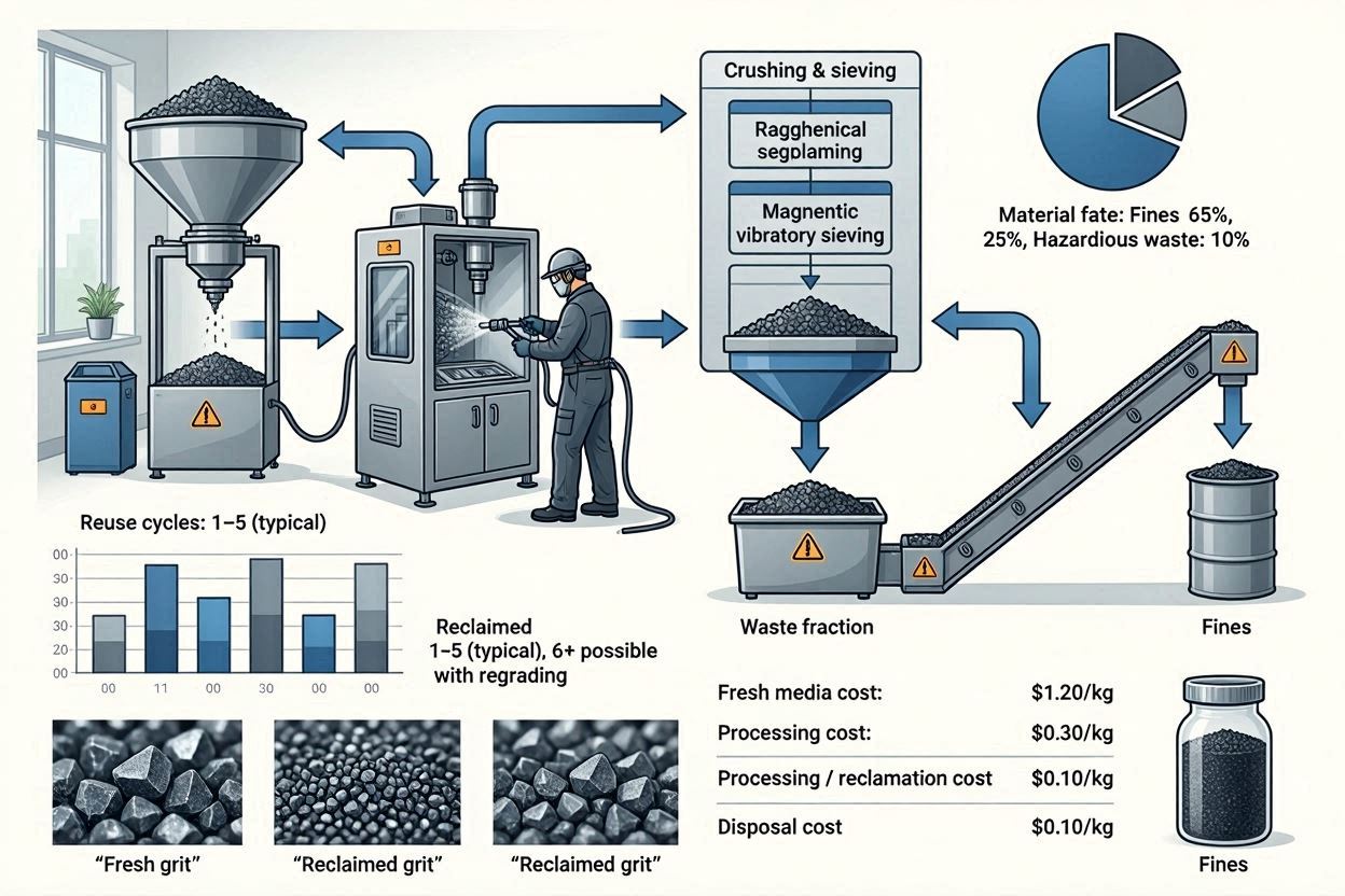
Yes, most facilities reuse ceramic media for multiple cycles with a classifier that removes undersized fragments. However, reuse has limits: as beads fracture, the angular fragments change the blasting characteristic and increase embedding risk. Set a maximum cycle count based on particle integrity observed in your process, and validate it. When in doubt, sieve the media and photograph the morphology.
What Ra should I target for cementless fixation?
There’s no single universal number, but clinical literature reviewed in the context of Clinical outcomes of ceramic bead surface treatment suggests an Sa in the 3–5 µm range with a developed interfacial area ratio (Sdr) above 20% works well for many titanium alloy stems. That’s a starting point—your design, loading condition, and coating strategy all shift the target.
Does bead size affect osseointegration?
Indirectly, yes. Bead size influences the peak‑to‑valley spacing and the density of dimples. Larger beads (200–350 µm) produce wider, deeper scallops that may aid initial mechanical interlock; smaller beads (50–100 µm) generate a finer finish that can benefit protein adsorption. The best approach is not to guess but to compare two bead size distributions head‑to‑head in a push‑out or pull‑off test on your specific implant geometry.
11. Pre‑Production Verification Checklist
✅ Before You Start a Ceramic Bead Blasting Run
| # | Checkpoint | Acceptance criteria / action |
|---|---|---|
| 1 | Media lot certificate reviewed | Purity ≥ 99.5%, particle size within ±15% of nominal, no silica contamination |
| 2 | Nozzle bore measured | Within 10% of new bore; no visible cracking |
| 3 | Blast cabinet cleanliness confirmed | No cross‑contamination of media from previous material; dust collector differential pressure in range |
| 4 | Air supply dry and oil‑free | Dew point ≤ ‑40°C; oil aerosol < 0.1 mg/m³ (ISO 8573‑1 class 2 recommended) |
| 5 | Part cleaning prior to blast | Water break test: continuous water film for ≥ 10 seconds |
| 6 | Fixture verified | Part seated firmly; no masking damage; robot path collision‑free |
| 7 | First article roughness measurement | Ra (or Sa) within validated window; 3 locations measured |
| 8 | Post‑blast cleaning solution ready | Ultrasonic bath freshly filled; passivation solution at correct concentration and temperature |
| 9 | Documentation package in place | Batch record, media lot number, operator ID, equipment parameters logged |
| 10 | Emergency stop and dust collection interlock tested | System halts immediately; alarm triggers if dust collector fails |
Surface treatment of orthopaedic implants with ceramic beads is a discipline where empiricism and rigor must coexist. When you combine careful media selection, robust process validation, and honest in‑process checks, the outcome is a surface that surgeons trust and patients rely on—without surprises at audit or retrieval.
Фильтры