Reducing Staircase Effect and Layer-Line Roughness on Titanium SLM Parts with Abrasive Finishing
The staircase effect is the most visible surface defect on SLM titanium parts and the primary reason as-built Ra values of 5–20 μm are incompatible with most engineering specifications. It is also the most tractable: unlike alpha-case or embedded satellite particles, the staircase profile can be systematically reduced by a graded abrasive sequence without requiring chemical processing or specialized equipment. This guide explains the geometry behind staircase roughness, how to estimate the target material removal per surface type, and how to design a graded blasting sequence that achieves the required Ra efficiently.
1. The Physics of the Staircase Effect in SLM
In any layer-by-layer manufacturing process, surfaces that are neither horizontal nor perfectly vertical are approximated by a series of discrete steps, one per layer. In SLM, the layer thickness t is fixed for a given build (typically 30–60 μm for titanium), and the step height at any angled surface equals the layer thickness. The width of each step depends on the build angle θ measured from the horizontal plane: step width = t / tan(θ). The resulting theoretical arithmetic mean roughness Ra of an untreated staircase surface can be estimated as:
Ra_theoretical ≈ t × cos(θ) / (2 × sin(θ))
Substituting practical values: at t = 40 μm and θ = 45°, Ra_theoretical ≈ 20 μm. At θ = 75°, Ra_theoretical ≈ 5.4 μm. At θ = 30° (a shallower overhang), Ra_theoretical ≈ 35 μm. These theoretical values are for perfectly stepped geometry; actual measured Ra on SLM titanium is typically 60–80% of the theoretical value because the melt pool creates slightly rounded step edges rather than perfectly sharp corners.
Critically, the staircase effect produces different Ra on different faces of the same part. A single titanium SLM bracket may have near-vertical walls with Ra 4–6 μm, angled overhang faces with Ra 12–18 μm, and horizontal top surfaces (upskin) with Ra 5–8 μm. Effective abrasive finishing must be calibrated for each surface type — applying the same protocol across all faces will either under-process the rough downskin surfaces or over-process the cleaner near-vertical walls.
2. As-Built Ra by Build Orientation: What to Expect
| Surface Type | Build Angle (° from horizontal) | Typical As-Built Ra | Typical As-Built Rz |
|---|---|---|---|
| Upskin (top face) | 90° (horizontal) | 4–8 μm | 25–50 μm |
| Near-vertical wall | 80–90° | 5–10 μm | 30–60 μm |
| Mid-angle overhang | 45–60° | 10–18 μm | 60–110 μm |
| Shallow overhang (downskin) | 20–45° | 15–25 μm | 90–150 μm |
| Horizontal downfacing | 0° (ceiling) | 18–30 μm | 100–180 μm |
Note that downskin surfaces are rougher than theoretical estimates based on geometry alone. This occurs because the downfacing surface is supported by loose powder rather than solid material during the build, and partially melted powder particles bond to the underside of the melt pool as it solidifies, adding a layer of bonded-powder roughness on top of the geometric staircase. This combination of staircase steps and bonded-powder roughness is what produces Ra values of 18–30 μm on horizontal downfacing surfaces, compared to the Ra 4–8 μm found on the same part’s upskin faces.
3. The Graded Blasting Strategy
A graded blasting strategy uses progressively finer media and lower pressure across two or three stages to systematically reduce the as-built staircase profile. The logic is straightforward: coarser media removes more material per pass (needed for rough downskin surfaces) but leaves its own roughness footprint that must then be smoothed by a finer stage. Each stage’s parameters are calibrated to a specific material removal target, and the sequence ends when the surface Ra meets the application specification.
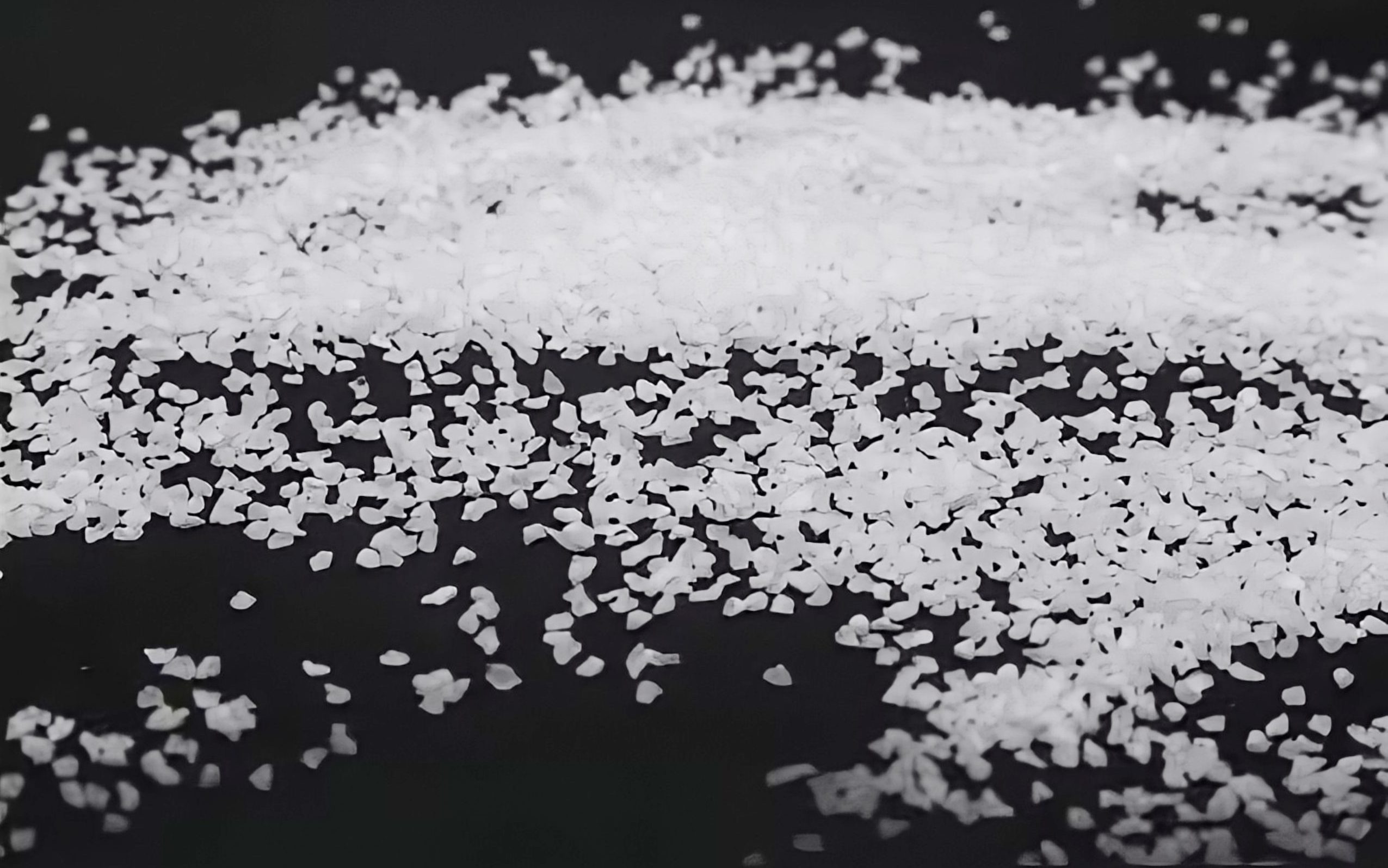
Stage 1 (roughness normalization): Angular Al₂OΆ grit 80–100 at 55–70 PSI. Targets the downskin and mid-angle surfaces where as-built Ra exceeds 10 μm. This stage breaks down the tall staircase steps and bonded powder, converting the highly directional staircase profile into a more isotropic blasted topography. Target Ra after Stage 1: 4–8 μm on all surface types. If upskin surfaces already meet the Stage 1 Ra target (they typically do), they can be skipped in Stage 1 to prevent unnecessary material removal.
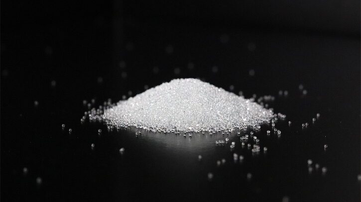
Stage 2 (surface quality improvement): Fine Al₂OΆ mesh 150–180 or glass beads mesh 120–150 at 40–55 PSI. Applied uniformly across all surface types after Stage 1 normalization, this stage reduces Ra from the 4–8 μm range down to 1.5–4 μm, depending on the media size and number of passes. This is the final stage for many industrial applications and serves as the preparation stage for aerospace shot peening.
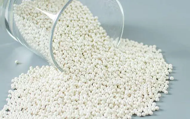
Stage 3 (precision finish, application-specific): Fine glass beads or zirconia beads mesh 200–280 at 25–45 PSI. For applications requiring Ra below 1.6 μm — medical implants, PVD coating preparation, tight-tolerance aerospace surfaces — a third stage with fine spherical media achieves Ra 0.8–1.6 μm from the 1.5–4 μm range produced by Stage 2.
4. Parameters by Surface Type
| Surface Type | Stage 1 Media | Stage 1 PSI | Stage 2 Media | Stage 2 PSI | Target Ra (after S2) |
|---|---|---|---|---|---|
| Upskin | Skip or Al₂OΆ 100 | 50–60 | Glass / Al₂OΆ 150 | 40–50 | 1.5–2.5 μm |
| Near-vertical wall | Al₂OΆ 80–100 | 55–65 | Glass / Al₂OΆ 150 | 40–55 | 1.5–3.0 μm |
| Mid-angle (45–60°) | Al₂OΆ 80 | 60–70 | Al₂OΆ 150 / glass 120 | 45–60 | 2.0–4.0 μm |
| Shallow overhang | Al₂OΆ 60–80 | 65–75 | Al₂OΆ 120 / glass 120 | 50–65 | 2.5–5.0 μm |
| Downfacing ceiling | Al₂OΆ 60 | 70–80 | Al₂OΆ 120 | 55–65 | 3.0–6.0 μm |
Standoff distance: 150–200 mm for all stages. Nozzle angle: 60–80° to surface (perpendicular impact at 90° drives embedment; angles below 45° reduce cutting efficiency on staircase steps). Traverse speed should be consistent within each stage — typically 150–250 mm/min — to maintain uniform dwell time and coverage across each surface area.
5. Ra Reduction Benchmarks: What Is Achievable
With the three-stage graded protocol above, the following Ra reductions are achievable on Ti-6Al-4V SLM parts built at 30–60 μm layer thickness:
- Upskin surfaces: as-built Ra 5–8 μm → after S2: Ra 0.8–1.5 μm; after S3: Ra 0.4–0.8 μm
- Near-vertical walls: as-built Ra 6–10 μm → after S2: Ra 1.0–2.0 μm; after S3: Ra 0.6–1.0 μm
- Mid-angle (45–60°): as-built Ra 10–18 μm → after S2: Ra 2.0–4.0 μm; after S3: Ra 1.0–2.0 μm
- Shallow overhang: as-built Ra 15–25 μm → after S2: Ra 3.0–6.0 μm; after S3: Ra 1.5–3.0 μm
These are achievable ranges, not guarantees. Actual outcome depends on machine-specific Ti powder quality, build parameters, layer thickness, and media condition. First-article trials are essential to confirm achievable Ra for each specific part and process combination. Surface roughness verification methods are discussed in detail in our guide on surface roughness measurement for abrasively finished titanium SLM parts.
6. When to Stop: The Over-Blasting Risk
Over-blasting is a common and costly error in titanium SLM surface finishing. Continuing to blast beyond the Ra target produces diminishing returns — Ra no longer decreases because the impact crater size from the blast media sets a physical lower limit on achievable roughness — while continuing to remove material from the part surface. On a precision component, this unnecessary material removal can push critical dimensions out of tolerance and invalidate all subsequent processing.
The practical rule is: measure Ra after each stage and stop as soon as the target Ra specification is met. In-process Ra checks after Stage 2 are particularly important because Stage 2 is where most parts reach or approach the specification. If Stage 2 achieves the specification, Stage 3 is unnecessary and should be omitted. Additionally, note that blast media in poor condition (excessive fines from media breakdown) produces a finer effective Ra than fresh media of the same nominal size — monitor media condition by particle size distribution sampling and replace when the fines content (≪40 μm) exceeds 10% by weight, which typically occurs after 400–600 cycles for Al₂OΆ and 800–1,000 cycles for glass beads.
For the complementary process of removing alpha-case that often coexists with heavy staircase roughness on the same surface, see our protocol for alpha-case removal from SLM titanium parts using abrasive blasting.
Часто задаваемые вопросы
Reaching Ra below 1 μm by blasting alone on titanium SLM parts is possible but difficult to sustain in production. With fine zirconia or glass beads in the mesh 220–320 range at 20–40 PSI in a wet blast process, Ra values of 0.4–0.8 μm can be achieved on upskin and near-vertical surfaces. On heavily staircased downskin surfaces, the physical limit set by the blast crater size typically limits blasting to Ra 1.0–1.5 μm at best. For applications requiring Ra below 1 μm on all surface types — PVD coating preparation, precision DLC deposition — a combination of blasting followed by vibratory finishing or electropolishing is typically required.
For a mid-angle overhang surface (Ra 15 μm as-built) using the two-stage protocol, expect: Stage 1 with Al₂O₃ grit 80 at 65 PSI — 3 to 5 passes to reduce Ra from 15 to 5–8 μm; Stage 2 with Al₂O₃ mesh 150 at 50 PSI — 2 to 4 passes to reduce from 5–8 to 2–4 μm. Total: 5 to 9 passes across two stages. These estimates assume a traverse speed of 200 mm/min and a fresh media charge. Worn media requires more passes; first-pass Ra reduction with worn media is typically 40–60% of fresh media performance.
In most cases, heat treatment should precede final abrasive finishing, for two reasons. First, stress relief annealing (typically 650–750°C for Ti-6Al-4V in vacuum or inert atmosphere) may cause minor microstructural changes at the surface that affect the finished surface texture if blasting precedes annealing. Second, if HIP is used as a post-processing step (900–955°C), the surface distortion from HIP consolidation changes the surface topography, making a pre-HIP final blast a wasted effort. The exception is the pre-HIP light satellite-removal blast, which is performed before HIP specifically to clear open pore mouths. Alpha-case removal should also occur before heat treatment if alpha-case is thermally induced, to minimize further oxygen ingress during heating.
Yes, directly. A thinner layer (30 μm) produces a smaller staircase step height and a correspondingly lower as-built Ra than a thicker layer (60 μm) at the same build angle. Practically: for parts built at 30 μm layer thickness on a downskin surface at 45°, as-built Ra is approximately 12–15 μm; at 60 μm layer thickness on the same surface, as-built Ra is approximately 20–28 μm. The thicker-layer part requires a more aggressive Stage 1 blast (coarser grit, higher pressure, more passes) to achieve the same final Ra. If your build machine and material combination support thinner layers, the reduced staircase roughness directly reduces the finishing burden and may allow omission of Stage 1 for most surface types.
Need Specialist Abrasive Media for Titanium SLM Finishing?
Jiangsu Henglihong Technology Co., Ltd. supplies the complete range of abrasive media for graded staircase reduction on titanium SLM parts — from grit 60 angular Al₂O₃ for Stage 1 roughness normalization through mesh 220 zirconia beads for precision Stage 3 finishing. Contact our technical team for a media grade recommendation specific to your build parameters and Ra target.
Contact Our Technical TeamФильтры