Ceramic Bead Blasting Process for Orthopedic Implants: Parameters and Best Practices
I’ve spent years on the shop floor dialing in blasting processes for hip stems, knee femoral components, and spinal cages. When someone asks me what separates a mediocre finish from a truly repeatable, regulatory-ready surface, the answer almost always comes down to parameter control and the discipline to stop guessing. This article covers exactly what I check, set, and troubleshoot when ceramic bead blasting orthopedic implants. Every recommendation here comes from real processing constraints — balancing roughness targets, cycle times, media breakdown, and cleanability.
1. Introduction to Bead Blasting in Medical Devices
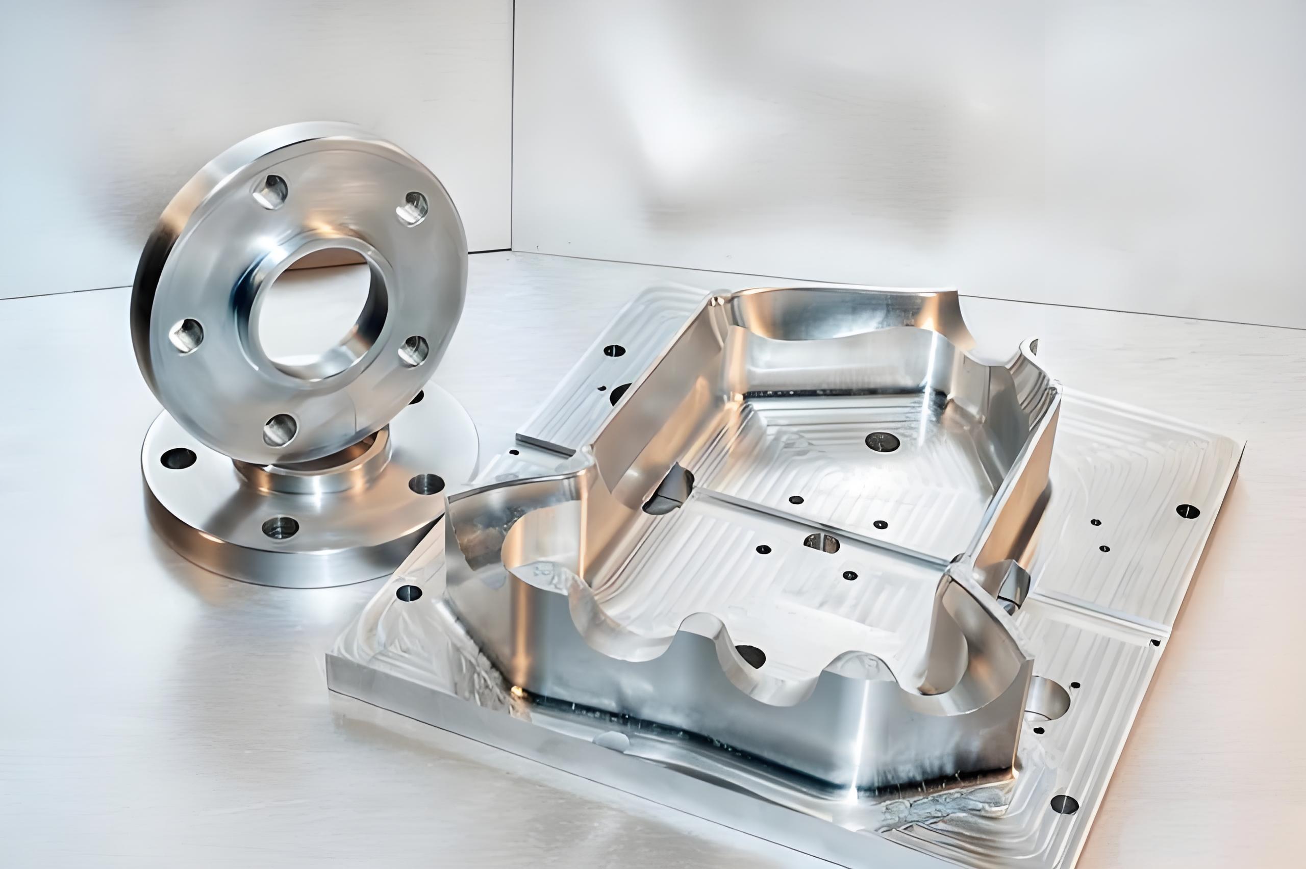
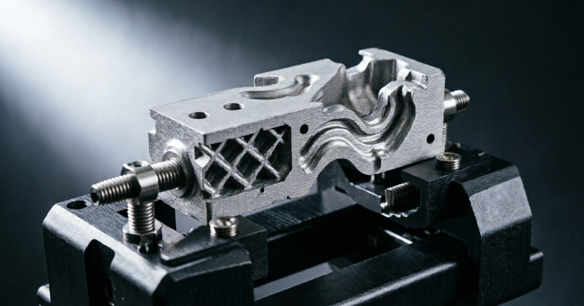
Ceramic bead blasting isn’t just a cleaning step. On orthopedic implants, it’s a surface engineering operation that simultaneously removes oxide layers, deburrs machined edges, and imparts a specific micro-texture. For many load‑bearing devices, the resulting roughness profile directly influences osseointegration, cement adhesion, or fretting behavior. That’s why I treat blasting with the same seriousness as a CNC finish pass.
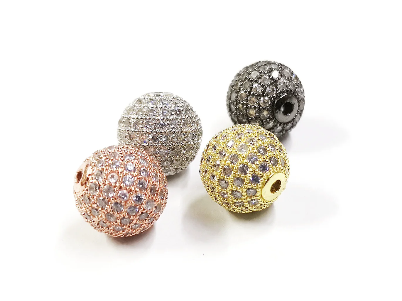
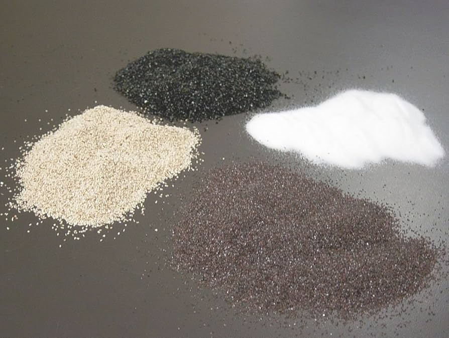
Unlike sandblasting with angular alumina, ceramic beads produce a more ductile, peening‑like impact. The spherical shape creates dimples rather than sharp cuts. This is critical when you need Ra values between 1.5 and 4.0 µm on titanium or cobalt‑chrome — tight enough for bone apposition, but without creating stress risers that could lead to fatigue crack initiation. If you’re new to the full landscape of ceramic bead applications for medical components, our Ceramic bead surface treatment guide lays out the material science and broader process benefits before you dive into these parameter-level details.
What makes blasting uniquely challenging in medical manufacturing is the documentation and cleanliness burden. You’re not only hitting a roughness number; you’re proving that the surface is free of embedded media, compatible with passivation, and consistent from lot to lot. I’ll address each of those layers as we move through the process.
2. Key Process Parameters (Pressure, Distance, Angle, Time)
Every blasting setup I evaluate starts with four interconnected variables. Change one without adjusting the others, and you’ll see roughness drift, uneven coverage, or excessive media fragmentation.
Давление взрыва
For ceramic beads (typically 100–200 µm) on Ti-6Al-4V or CoCr, I operate in the 2.5–5.0 bar (35–70 psi) range. Below 2 bar, dimple formation is inconsistent, and you risk failing to remove machining lines. Above 5 bar with standard suction or pressure‑pot systems, I start to see bead shattering and higher embedment risk. The best balance I’ve found for controlled Ra increase (from ~0.8 µm as‑machined to ~2.5 µm) sits at 3.5–4.0 bar with a 150 µm bead.
Watch-out: If the pressure gauge flickers or drops more than 0.3 bar during a cycle, stop immediately. That fluctuation often means a clogged nozzle, moisture in the media, or a compressed air supply issue. You’ll never get repeatable roughness with a nervous pressure curve.
Nozzle-to-Part Distance
Maintain 100–200 mm for most implant geometries. Closer than 80 mm risks localized cold work and excessive material removal; further than 250 mm, and impact energy drops enough to leave shiny areas after processing.
On complex concave surfaces like the inner pocket of a tibial tray, I often reduce distance to 90–120 mm but lower pressure to 2.8 bar to avoid dwell‑time hotspots. A useful field check: blast a flat coupon at your planned distance. If the impact pattern shows a distinct bright center ring surrounded by a hazier halo, your standoff is too short — that’s the bead plume creating an uneven energy distribution.
Angle of Incidence
Aiming perpendicular (90°) gives maximum dimple depth and fastest roughness generation. However, I rarely stay exactly at 90° for more than a sweep. For uniform coverage on multi‑axis features, I vary between 75° and 90°. Angles below 60° start to smear instead of dimple, especially on softer titanium alloys, so I avoid oblique blasting unless I’m intentionally creating a directional finish.
Automated rotary fixtures help, but when manual blasting is the only option, train operators to use a consistent pendulum motion, not a fixed‑angle static hold.
Dwell Time and Coverage
Time is the most abused parameter. Instead of saying “blast for 30 seconds,” I define coverage in visual terms: a uniform matte finish with no shiny base‑metal reflections. On a typical hip stem, that translates to 12–18 seconds of active nozzle exposure per side at 4 bar. Doubling time to hit a deeper Ra often backfires — it comminutes media, embeds fragments, and rolls the surface without useful roughness gain.
For production, I use a timer interlock. Once coverage is visually achieved, I run exactly that cycle duration plus a 10% over‑blast factor to account for slight fixture variation. Any operator going markedly beyond that needs to flag the part.
| Параметр | Typical Range (Orthopedic) | Preferred Setpoint (Example: Ti‑6Al‑4V, Ra 2.5 µm) | When to deviate |
|---|---|---|---|
| Pressure | 2.5 – 5.0 bar | 3.8 bar | Use lower end for thin walls (<1.5 mm); higher end for heavy CoCr stock removal |
| Nozzle distance | 100 – 200 mm | 140 mm | Reduce to 100 mm for deep concave areas but lower pressure proportionally |
| Angle | 75° – 90° | 85° | Keep above 75° to avoid surface smearing; 90° only with constant motion |
| Dwell time (per zone) | 10 – 25 seconds | 16 seconds | Validate by visual coverage check plus profilometer reading |
| Media flow rate | 3 – 6 kg/min (pressure pot) | 4.5 kg/min | Adjust with nozzle bore wear; monitor by weighing media consumed per cycle |
3. Ceramic Bead Size and Shape Selection
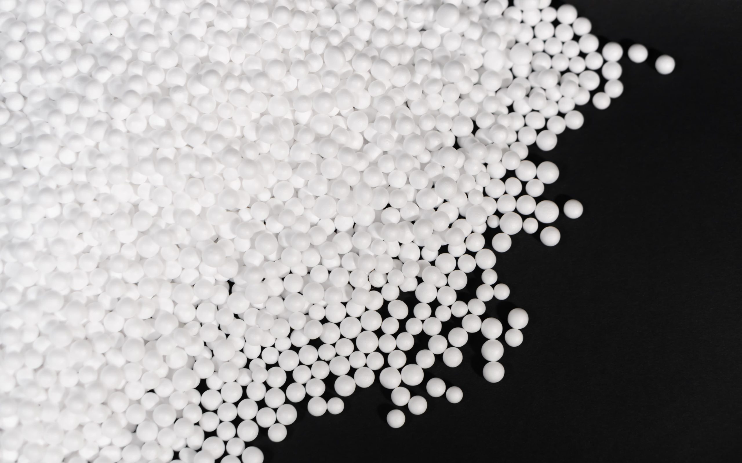
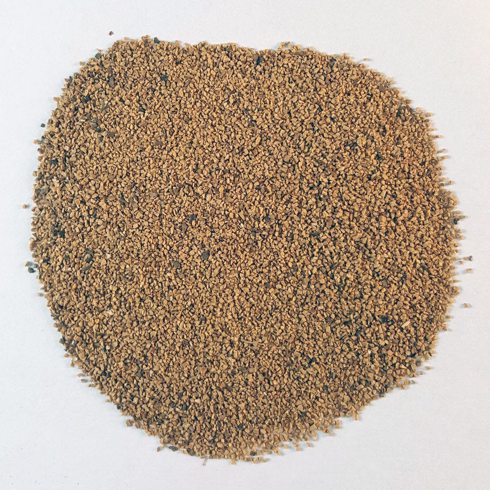
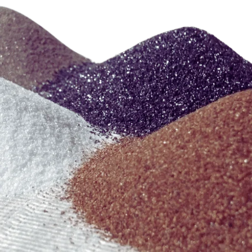
Zirconia‑based ceramic beads dominate medical blasting because of their inert chemistry and fracture toughness. But size and shape specifications directly control what kind of surface you’ll produce — and how much downstream cleaning you’ll need.
Bead Diameter: 100 µm vs. 150 µm vs. 200 µm
I stock three bead sizes for orthopedic work: 100–125 µm for fine finish on spinal cages, 125–180 µm for general femoral and tibial components, and 180–212 µm only for aggressive texture on grit‑blast‑equivalent surfaces where the design calls for Ra >3.5 µm. Smaller beads produce a higher density of shallower dimples, which improves wettability without raising Ra beyond 2.0 µm — a sweet spot for cementless implants where you want protein adsorption but not micro‑movement risk.
Larger beads create a deeper, more open texture but also raise the probability of edge rounding on sharp threads. I’ve seen bone screw cancellous threads lose their cutting profile when blasted too aggressively with 200 µm media. That’s a good reason to have size‑specific recipes locked in your control plan.
Shape: True Spheres vs. Irregular Particles
Only spherical beads should be used for implant surfaces intended for tissue contact. Irregular or fractured particles act like angular abrasives — they cut rather than peen, leaving sharp valleys that can trap cleaning agents or promote pitting. A quick way to check shape integrity in‑process: take a media sample and inspect under 20x magnification. If more than 5% of particles appear fractured or elongated, replace the charge.
Fresh vs. Work‑hardened Media
Brand‑new media tends to be slightly more aggressive for the first 2–3 cycles. I “break in” a fresh charge by blasting scrap Ti coupons until the Ra stabilizes. Only then do I switch to production parts. This prevents lot‑to‑lot roughness drift.
4. Effect on Surface Roughness and Cleanliness
Surface roughness after ceramic bead blasting isn’t only about Ra. I always measure Rz and RSm as well, because two surfaces with identical Ra can behave very differently in cell adhesion or cement interlock.
Typical Roughness Outcomes
Starting from a machined surface of Ra 0.6–1.0 µm, a well‑controlled ceramic bead blast with 150 µm media at 3.8 bar typically yields an Ra of 2.2–3.0 µm and Rz of 12–18 µm. The peak‑to‑valley distribution is isotropic, which matters for osseointegration. I’ve documented roughness data on hundreds of test coupons — the key is that Rz/Ra ratio stays around 5.5–6.5. If that ratio climbs above 7.5, it usually indicates bead fracture or contaminated media creating outlier deep scratches.
Cleanliness: Beyond Visual Inspections
Embedded ceramic particles are a common rejection cause. Standard passivation (nitric acid) won’t remove ceramic; it only passivates the metal around the particle, potentially leaving it loose. I’ve found that a multi‑stage ultrasonic cleaning sequence after blasting — alkaline detergent at 60°C, followed by deionized water rinses, then citric acid passivation — drops particle counts to acceptable levels, but only if the blasting parameters were already right. Over‑blasting at high pressure forces beads into the surface and makes cleaning nearly impossible. If I see white specks under 30x after passivation, my first suspicion is excessive pressure or extended dwell time — not the cleaning line.
For a rigorous cleanliness check, I sometimes use adhesive tape lift testing (per ASTM F2847) or SEM/EDS. But consistently hitting a clean surface starts at the blasting cabinet, not in inspection.
5. Equipment and Set-up for Medical Blasting
A standard industrial sandblasting cabinet isn’t enough. Medical‑grade blasting environments need contamination control, dust extraction validated for implant production, and exact repeatability.
Cabinet and Environmental Controls
- Pressure‑pot system with a precision regulator (deviation ≤0.1 bar). Suction systems I avoid for medical work — they’re too sensitive to media level and humidity.
- HEPA‑filtered dust collector and a cyclone separator to remove fine media fragments continuously. Sieve the media every 8 hours of run time minimum.
- Clean, dry compressed air (ISO 8573-1 Class 1.4.1 or better). I recommend a refrigerated dryer followed by a desiccant dryer with a dew point monitor. Any moisture and you’ll get media clumping, which changes flow rate and impact energy.
- Part fixturing that allows consistent positioning without shadowing. For high‑volume femoral stems, I now use robotic arms with pre‑programmed paths; for lower volumes, a manually indexed rotary table with proximity stops still works.
Nozzle Selection and Maintenance
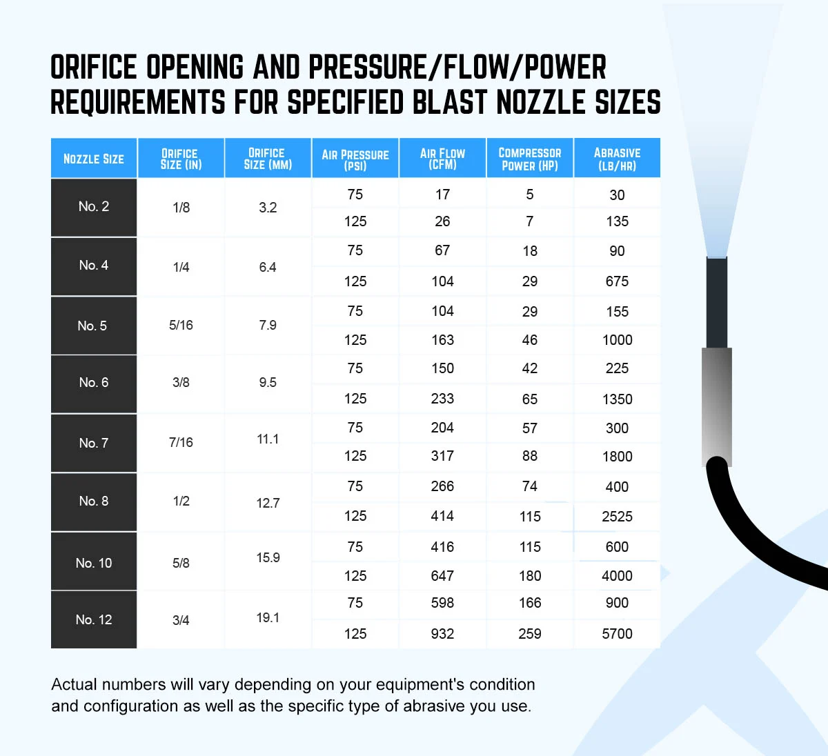
Venturi‑type boron carbide nozzles, 8–10 mm bore diameter, are my go‑to. They accelerate beads efficiently and resist wear longer than tungsten carbide. However, as the nozzle bore enlarges (check every 40–50 hours of blasting), the velocity at a given pressure drops and the plume widens. I track nozzle bore diameter with a go/no‑go gauge weekly. When the bore exceeds 10% of original diameter, replace it. Don’t compensate by increasing pressure — that’s a recipe for parameter creep.
6. Process Validation and Repeatability
Validation for ceramic bead blasting follows the same IQ/OQ/PQ framework as any special process in medical device manufacturing. But the nuances matter.
Installation Qualification (IQ)
Verify that the air supply meets the required quality class, the cabinet maintains negative pressure, the dust extraction is working, and the media batch is certified (composition, size distribution, cleanliness). Document it all.
Operational Qualification (OQ) – Challenge the Limits
I run a designed experiment varying pressure (±0.5 bar), distance (±30 mm), and bead lot. Using flat Ti coupons (minimum 30 samples), I blast at the nominal, low, and high extremes and measure Ra, Rz, RSm, and particle contamination via tape lift. If any extreme condition produces an out‑of‑spec roughness or visible embedment, I narrow the process window right there.
For example, if the pressure high limit (4.5 bar) pushes Ra to 3.8 µm and leaves ceramic fragments, I cap the alarm limit at 4.1 bar and set the control limit at 3.8 bar. You want a window, not a cliff edge.
Performance Qualification (PQ) and Ongoing Control
PQ should mimic actual production — same fixtures, part orientations, and cycle times. I typically take roughness measurements on three locations per part (proximal, mid, distal) for at least 10 parts. The standard deviation of Ra across all locations should be ≤0.25 µm for a well‑tuned process. If it’s higher, revisit fixture motion or nozzle alignment.
For ongoing control, use statistical process control (SPC) charts on Ra and Rz from a sacrificial coupon included with every production lot. If the coupon Ra trends upward over successive runs, it often signals media aging or nozzle wear.
| Problem | Likely Causes (in order of suspicion) | Immediate Action | Long‑term Fix |
|---|---|---|---|
| Ra too high / inconsistent | High pressure, nozzle too close, media fracture, worn nozzle creating uneven velocity | Reduce pressure 0.3 bar, check nozzle bore, screen media | Implement nozzle replacement schedule; install media classifier |
| Shiny spots (under‑blasted) | Shadowing, insufficient dwell time, media flow blockage, low pressure | Inspect fixture shadow areas; increase cycle time 15% | Re‑design fixture for line‑of‑sight; add air jet vibrator to media hopper |
| Embedded ceramic particles | Excessive pressure, dwell time too long, worn media generating fines | Lower pressure to minimum within window; check ultrasonic cleaning sequence | Reduce dwell time; replace media charge; validate with tape test |
| Rust spots on stainless steel or CoCr | Contamination from carbon steel tooling or air line corrosion | Check tooling material (must be stainless); test air for rust particles | Switch to all‑stainless fixturing; add coalescing filter on air line |
| Roughness drift over production day | Media aging, humidity causing clumping, nozzle wear | Change or sieve media mid‑shift; check dew point | Add real‑time dew point alarm; define media life in operating hours |
7. Common Challenges and Troubleshooting
I’ve grouped the most frequent headaches into practical fixes. If you’re standing at the blasting cabinet right now because a lot just failed a roughness check, start with pressure and media condition — that solves 70% of problems.
Roughness variation across a single part
This usually signals fixture orientation or robotic path issues. Manually blast a part while slowly rotating it and note where the finish dulls. If the variation is proximal‑to‑distal, the distance was inconsistent during the sweep. Adjust the robot’s TCP speed or the manual dwell pattern.
Media clumping and irregular flow
Clumping almost always traces back to moisture. Even a 2% moisture content can cause catastrophic bridging. I install a dew point sensor immediately before the blast pot and set an alarm at −20°C dew point. If the alarm trips, stop production — don’t rely on “it feels dry.”
Excessive dust inside the cabinet
Dust reduces visibility and deposits fines on parts. If your dust collector differential pressure gauge shows >150 mm H₂O above clean filter reading, the filters need cleaning or replacement. High dust also signals media breakdown; pull a media sample and measure the percentage of particles below 50 µm. If it exceeds 8–10%, dump and recharge.
Pre‑production Blasting Checklist
Before you start the next implant lot, verify these 10 items
- Air supply dew point ≤ −20°C and pressure stable within ±0.1 bar at setpoint
- Nozzle bore diameter measured and within wear tolerance (original +10% max)
- Media batch certified; no visible fractured particles in recent sample
- Dust collector differential pressure within spec; cyclonic separator bowl empty
- All fixturing is dedicated stainless steel or titanium — no carbon steel anywhere
- Validation coupon ready for roughness verification (same alloy, same orientation)
- Blasting cabinet gloves and seals inspected; no signs of ingress contamination
- Ultrasonic cleaning tanks prepared with correct detergent concentration and temperature
- Profilometer calibrated and stylus clean (Ra, Rz, RSm measurement plan pre‑loaded)
- Production traveler or batch record open with blasting parameters clearly specified
Часто задаваемые вопросы
Can I use the same ceramic bead blasting parameters for titanium and cobalt‑chrome?
Not without adjustment. Cobalt‑chrome is harder and requires slightly higher pressure (typically +0.3–0.5 bar) to achieve the same Ra with the same media. Always characterize roughness on separate alloy‑specific coupons, even if the bead size is the same. I keep distinct recipe files for Ti and CoCr families.
How do I know when ceramic beads are worn out?
Two indicators: a gradual increase in surface roughness standard deviation, and a rise in fine dust (particles <50 µm) above 10% of the media charge. If you need to increase blasting time to hit the same visual coverage, that’s another sign. I replace the charge proactively at 40–60 operating hours, depending on bead size.
Is it possible to skip passivation after ceramic bead blasting?
No. Blasting exposes fresh metal and can embed contaminants. Passivation (nitric or citric) is essential to restore the passive oxide layer and remove iron contamination. The sequence matters: clean, blast, clean again, passivate. Never passivate immediately after blasting without an intermediate cleaning step, or you risk masking residues.
What’s the most reliable way to measure roughness for regulatory submission?
Use a contact profilometer with a 2 µm radius stylus, measuring at least three non‑overlapping 4 mm traces per area of interest. Report Ra, Rz, and RSm. For complex shapes, complement with optical profilometry (confocal or interferometry) to show isotropic topography. Document the cutoff wavelength (λc) — typically 0.8 mm for blasted surfaces.
Blasting is a special process because the result can’t be fully verified without destructive testing. That’s why parameter control is everything. Master the interactions between pressure, distance, bead size, and time, and you’ll ship surfaces that are predictable, clean, and auditable — every single lot.
Фильтры